Navigation
Tip correct definition
After a rack change of either a REVO stylus holder or a TP20 module with PH20 the probe may not be seated in exactly the same position as it was when that tool was calibrated. These fractional variations in assembly alignment can have a small effect on overall system accuracy. This is due to the repeatability of the kinematic joint between the probe and module / stylus holder.

Tip correction allows adjustments to be made for this small positional deviation, optimising metrology accuracy for the tool involved.
There are two situations in which a tip correction sequence will be performed:
- Performing a ChangeTool() that results in a physical assembly change
- Calling the Renishaw specific I++ command RWRequalify(TipCorrect())
The tip correction procedure will only be performed on tools that are currently calibrated, and the process may be enabled or disabled on a tool by tool basis, by setting the Tool's TipCorrect.Enabled option to true or false respectively. The TipCorrect.Enabled option is found in UCCserver on the Advanced Tab under Environments -> Your environment -> Tools.
The tip correct procedure
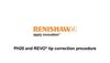
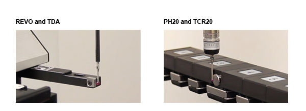
In order to use the tip correct functionality you will require either a TDA for use with REVO or the TCR20 rack for use with PH20.
Performing a tip correction
The tip correction sequence is as follows:
- If calling RWRequalify(TipCorrect()) the probe moves to the calibration plane's safe point and rotates to (A:0, B:0).
- The probe then moves close to the calibration plane, the actual distance being defined by the tool's PtMeasPar.Approach property. If performing a tool change, the probe will move directly to this point after picking up the new tool assembly.
- The probe then rotates to A:0, and a B angle such that when the probe swings negatively on the A-axis and contacts the front surface of the calibration plane, the line it follows will be normal to the calibration plane's front face.
- The probe then swings in negative A to take a set of multiple touch points against the calibration plane. The default number of touch points is 4 but this number can be configured on a tool by tool basis by changing the Tool's TipCorrect.NPoints.Act parameter which is found on the Advanced Tab under Environments->Your environment->Tools immediately below the TipCorrect.Enabled option.
- The tool then returns to A:0 and rotates 180 degrees on the B-axis.
- The probe now takes multiple touches in the positive direction against the calibration plane
- If calling RWRequalify(TipCorrect()) or if performing a tool change that involves no tool racks, the probe returns to the calibration plane's safe point. If performing a tool change that involves a tool rack, the probe returns to the tool rack's safe point.
- The probe rotates to the active tool's head orientation.
When the correction process is completed, the tip correction improvement is automatically applied to all head orientations for that tip.