Navigation
AC3 analogue interface PC card
Specifically designed for use with SP25M
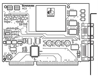 16-bit IBM ISA bus plug-in PC card with two external connectors capable of giving better than 0.1 μm resolution
- Simple to install and connects directly to a standard Renishaw multiwire probe signal cable
- Performs probe management functions
- Communicates status information to the host PC
- Converts each of the SP25M analogue probe axis outputs into 2's complement binary numbers accessible to the PC
- Optically isolated PICS (Renishaw's probe interconnection system) interface
- Reading synchronisation using the PICS interface or software commands
- Probe power removal using PICS
- Full ISA bus address decoding
- Optional 16-bit data transfers via the additional ISA 36-way connector
- Interrupts generated on receipt of PICS or software AQUIRE command
- The AC3 contains a number of registers that are accessible to software using I/O commands
- ΔT controller compatibility is achieved by the use of option switches
- AC3 also has its own board identification, which it presents to software
- SP25M and AC3 have been designed with a probe identification resistance of 9.375 kΩ
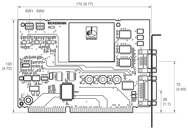
Dimensions
- An optional 16-bit or 8-bit ISA bus Interface in I/O space
- An option to connect to a ΔT controller (customer supplied wiring adaptor required)
- Three measurement channels (p, q, r), with a resolution of 16 bits
- 6 software selectable operating modes
- Hardware synchronisation of data acquisition in 5 of the operating modes
- ISA bus interrupt on data acquisition (in mode 3)
- Probe power supply protection with resettable fuses
- Paged version identification at the AC3 board identification register
- Integral measurement timer
- Detection of a connected SP25M
- Over-range input
ISA / ΔT bus interface
The AC3 address space is in I/O space when the ISA bus is selected. Accesses in memory space are not permitted. The bus interface can operate with 8-bit data (bytes) or 16-bit data (words). Selection of the ISA/ ΔT busses, base address and 8/16-bit modes are with selection switches.
Measurement channels (‘p', ‘q' and ‘r')
These have 16-bit resolution. Each time the ACQUIRE bit (bit ‘11' of register ‘13') is written to with a ‘1', or the appropriate synchronisation hardware is activated, the SP25M axis deflections are acquired and presented in registers ‘5' to ‘0', and the time latched into registers ‘7' and ‘6'.
Integral measurement event timer
This timer has a resolution of 256 microseconds and a maximum value of 16.78 seconds. The timer count register is updated every time the SP25M deflections are acquired. The timer can be reset to zero when the RESET TIMER bit (bit ‘8' of register ‘13') is written to with a ‘1'. If the timer reaches its maximum count value of 65536, the TIMER OVERFLOW bit is set to ‘1'. This can be inspected by reading the AC3 status register (bit ‘5' of register ‘14'). The TIMER OVERFLOW bit is reset to ‘0' when the timer is reset.
Detection of a connected SP25M
This is carried out automatically by the AC3. When the AC3 recognises that it is connected to an SP25M probe, it applies power to it. Software can inspect whether a probe is fitted by first writing a ‘1' to the REQUEST SET PROBE PRESENT bit (bit ‘10' of register ‘13'), then reading the PROBE PRESENT bit in the status register (bit ‘4' of register ‘14'). When the SP25M is removed, the PROBE PRESENT bit will be reset to ‘0' automatically. This feature is included so that software can detect that a probe has been disconnected, then reconnected since the PROBE PRESENT bit was last inspected.
Probe power supply protection with failure monitoring
The probe's power supplies are protected from overcurrent by self-resetting fuses (polysilicon current limiting devices) in each supply line. When an overcurrent occurs, the AC3 automatically removes all power from the probe and sets the appropriate OVERCURRENT bit. Software can inspect the status of these bits by reading the AC3 status register (bits ‘0', ‘1' and ‘2'. of register ‘14').
AC3 board identification byte
Software is able to read this byte at any time when the page register (‘base + 8') is set to 00H, to confirm that the adaptor board fitted at the expected base address is indeed AC3. Upon power up, the page register is set to 00H allowing software to read this identification byte without writing to the board. The AC3 identification byte varies, depending upon the selected bus width of the AC3. When it is in 8-bit mode, the ident is 0AH. In 16-bit mode, the ident is 09H. Most Renishaw ISA bus adaptor cards have a unique board identification byte at the address ‘base + 15'.
AC3 board functionality version number byte
The AC3 (like Renishaw's AC2 card) has software readable, version numbering. Often, changes to the hardware are invisible to the customer, such as when a component that is no longer available causes the design to be changed, so changes to the hardware that cause a consequential change to the customer's software cause the FUNCTIONALITY VERSION number to be incremented.
When the page register has been written to with 02H, the FUNCTIONALITY VERSION number can be read from ‘base + 15'. The functionality version is incremented by Renishaw when a change has been made to the design that requires a change to the customer software.
Part number | |
SP25M interface card | |
| AC3 ISA interface card for use with SP25M | A-2237-1601 |