Navigation
Gear / spline technical overview
Gear and spline inspections in MODUS are licensed options, available from the gear / spline option on the main toolbar. These options allow you to add commands to your part program for inspecting gears and splines, and to analyse the results. Gear and spline inspections are performed using a scanning probe such as the REVO® RSP3 probe module.
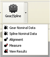
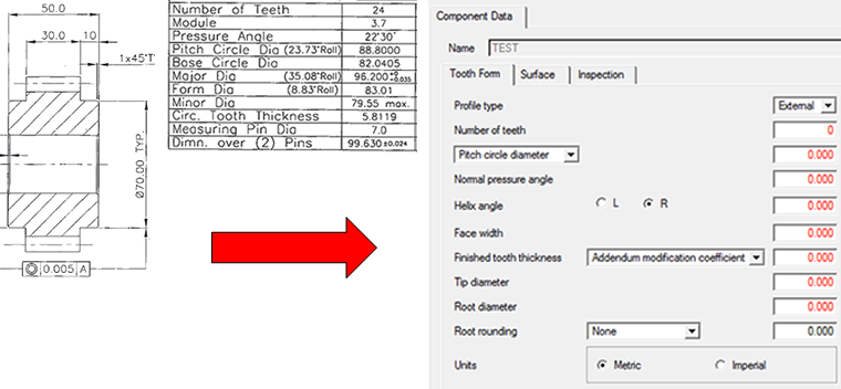
The first time the user selects the ‘Gear Nominal Data' option, they will be prompted to create a new nominal data file. The gear nominal data should be extracted from its data sheet and input to the ‘Component Data' fields.
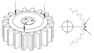
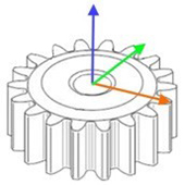
The alignment option from the drop-down menu will automatically generate the necessary code for gear specific alignment. Prior to this the user must complete a manual and CNC alignment by taking the points as shown on the diagram below. The two points taken either side of the gear tooth will be selected through the user interface to generate the gear specific alignment.
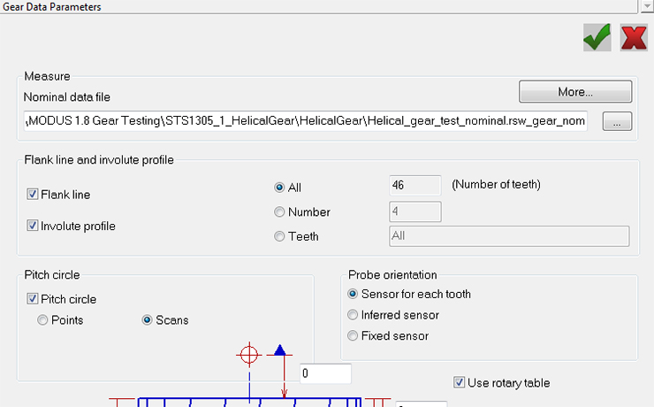
The code for gear measurement can be generated automatically through the measure option by reselecting the gear nominal file. Certain characteristics such as face width, midpoint for the profile and pitch inspection position are generated and used in measurement calculations. Measurement options such as flank line (scan along the length of the face width) can be chosen or parameters such as number of teeth can be changed through the UI. In addition to this, probe orientation can be altered so that the sensor angle is fixed or individual for each tooth, depending on the head and probe set up.
The results option in the drop-down menu allows the user to view the results of the inspection by selecting the corresponding ".RES" file. Several evaluation options such as profile / lead, pitch summary, pitch error, runout and tooth thickness can be checked to view graphical representations of the results.
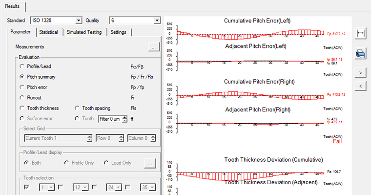
GEAR STANDARDS SUPPORTED | ISO 1328 | DIN 3961 | AGMA 2015-1-A01 |