Navigation
Change cycles
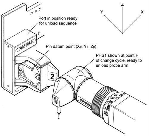
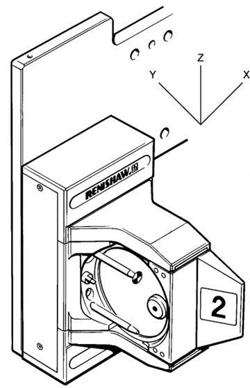
To change probe arms automatically using the ACR2, the CMM must be programmed to complete a series of movements using the positions given in this section. When manually loading the arm into the autochange rack, care must be taken to ensure that the port is locked in the uppermost position.
The coordinates of the positions given in this section are relative to the coordinate system defined on the pin datum point XD,YD,ZD calculated in the previous section.
Change cycle:
NOTE: D and E axes in correct orientation for change cycle (D0, E-90)
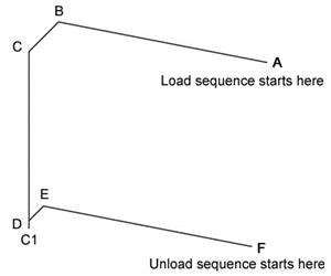
Load sequence:
Axis orientation:
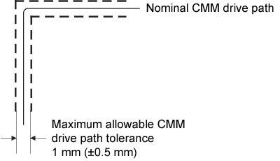
The following figure shows the maximum tolerance acceptable on the CMM drive path during the automatic change cycle.
Nominal CMM drive path:
The table below gives coordinates for the points in the automatic change cycle relative to the pin datum point XD,YD,ZD.
PHS1 axis origin position relative to pin datum point XD,YD,ZD:
Point | X | Y | Z |
|---|---|---|---|
A | +74 | -135.5 | +68.5 |
B | +74 | +14.5 | +68.5 |
C | +50 | +14.5 | +68.5 |
C1 | +50 | +14.5 | -35.5 |
D | +50 | +14.5 | -31.5 |
E | +53.5 | +14.5 | -31.5 |
F | +53.5 | -135.5 | -31.5 |
The following table gives the incremental values for the moves between points in the automatic change cycle:
Moves in automatic change cycle:
Move | Axis | Incremental value | Function |
|---|---|---|---|
A to B | Y | +150 | PHS1 moves in (or out of) port without probe arm loaded |
B to C | X | -24 | PHS1 latches (or unlatches) port with probe arm unlocked |
C to C1 | Z | -104 | Arm locking move (load cycle only) |
D to C | Z | 100 | Arm unlocking move (unload cycle only) |
C1 to D | Z | +4 | Locking mechanism backoff (load cycle only) |
D to E | X | +3.5 | PHS1 latches (or unlatches) port with probe arm locked |
E to F | Y | -150 | PHS1 moves in (or out of) port with probe arm locked |