Navigation
Change cycles
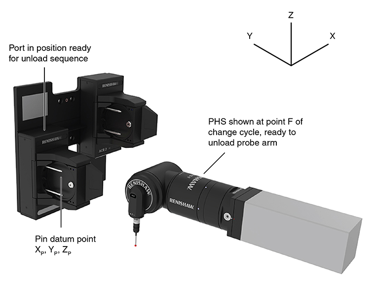
The co-ordinates of the positions given in this section are relative to the coordinate system defined on the pin datum point XD, YD, ZD calculated in the previous section.
Change cycle:
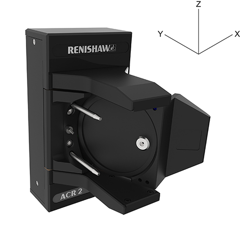
NOTE: D and E axes in correct orientation for change cycle (D0, E-90).
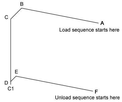
Load sequence:
Axis orientation:
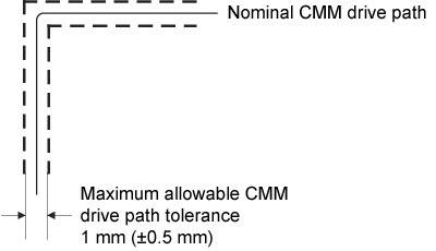
The following figure shows the maximum tolerance acceptable on the CMM drive path during the automatic change cycle.
Nominal CMM drive path:
The table below gives co-ordinates for the points in the automatic change cycle relative to the pin datum point XD, YD, ZD.
PHS-2 axis origin position relative to pin datum point XD, YD, ZD:
Point | X | Y | Z |
A | +74 | -135.5 | +68.5 |
B | +74 | +14.5 | +68.5 |
C | +50 | +14.5 | +68.5 |
C1 | +50 | +14.5 | -35.5 |
D | +50 | +14.5 | -31.5 |
E | +53.5 | +14.5 | -31.5 |
F | +53.5 | -135.5 | -31.5 |
The following table gives the incremental values for the moves between points in the automatic change cycle:
Moves in automatic change cycle:
| Move | Axis | Incremental value | Function |
| A to B | Y | +150 | PHS-2 moves in (or out of) port without probe arm loaded |
| B to C | X | -24 | PHS-2 latches (or unlatches) port with probe arm unlocked |
| C to C1 | Z | -104 | Arm locking move (load cycle only) |
| D to C | Z | 100 | Arm unlocking move (unload cycle only) |
| C1 to D | Z | +4 | Locking mechanism backoff (load cycle only) |
| D to E | X | +3.5 | PHS-2 latches (or unlatches) port with probe arm locked |
| E to F | Y | -150 | PHS-2 moves in (or out of) port with probe arm locked |