Navigation
Connections
Encoder connectors
The encoder interfaces are a machine installer configurable option, they permit the connection of digital encoders to the SPA2-2 and UCC2, UCClite or UCC BI system to provide motor feedback for inclusion into the machines control loop.
For further details on these connections please refer to 'Encoder interface' section.
Motor connector
These connections are used for the dc motor connector kit placement or brushless motor.
Axis position 3 is for the additional axis interface card that can be fitted by the machine installer to the SPA2-2 unit.
For further details on these connections please refer to 'Motor connectors' section.
Controller E-STOP connection
This 9-way 'D' connector links the emergency stop system between the SPA2-2 and the UCC2-2 / UCC BI controller, the necessary cable for this connection is supplied within the SPA2-2 kit.
SPA, -A, -B, -C, -D connections
These RJ45 connections permit the dedicated servo system communication link between the SPA2-2 and the UCC2, UCClite or UCC BI controller for an effective control system.
NOTE: Connections A and B are used for a three or four axis SPA2-2 system, connections C and D are only used when a six or seven axis system is contained within a single box. Refer to 'Interconnection schemes' section for further details.
External emergency stop connection
This 9-pin D-type connection is designed to permit connection of external emergency stop devices to the Renishaw controller emergency stop system.
The machine manufacturer or product installer must perform a risk assessment to determine the requirements for emergency stopping and emergency switching off.
To meet a higher performance level an external safety system must be fitted.
There are four connection pins available on this connector as shown below:
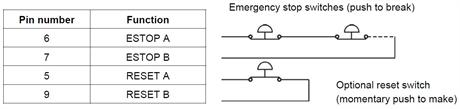
A manual reset button (refer to BS EN ISO13849-1:2015 (or current version) para. 5.2.2.) shall be included in the emergency stop system when required by the user's risk assessment. A reset switch may be needed when there is limited visibility of the danger zone from the machine's control position.
Reset switches must be located with full visibility of the danger zone and shall be sited outside the danger zone.
Any emergency stop device added to the E‐STOP chain must have an electrical rating of at least 24 V 1 A and meet the requirements of BS EN ISO 13850:2015 (or current version).
The emergency stop device shall have direct opening action with mechanical latching. The emergency stop devices shall comply with BS EN 60947-5-5:1998+A2:2017 (or current version).
All connections to the bypass plug shall be fitted by an electrically competent person and all wires are to be sleeved.