Navigation
E-STOP
The E-STOP connector is provided to allow connection of an external EMERGENCY STOP switch into the UCC T3 system. The machine manufacturer or product installer must perform a risk assessment to determine the requirements for emergency stopping and emergency switching off. The UCC T3 emergency stop safety system is designed to achieve category 2 or category B implementation as selected by the installer's risk assessment (refer to BS EN ISO13849-1:2008 para. 5.2.2).
The connection on the UCC T3 is a 9WD plug connector with the following connections:
Pin number | Function | Pin number | Function |
|---|---|---|---|
1 | E-STOP A (+24 V) | 6 | E-STOP A (+24 V) |
2 | Not connected | 7 | E-STOP B2 |
3 | 0 V | 8 | Not connected |
4 | E-STOP B1 | 9 | RESET |
5 | Not connected |

E-STOP connector - view on face of socket (rear of plug)
E-STOP electrical characteristics
Any emergency stop components fitted to this connector must have the following electrical characteristics:
Emergency stop system voltage: 24 V
Emergency stop system current: 1 A
All connections to this connector should be fitted by a competent technician or engineer and all wires should be sleeved. Any emergency stop devices added to the E-STOP chain should meet the requirements of IEC 60947-5-1 (Low-voltage switchgear and control gear – Part 5-1: Control circuit devices and switching elements – Electromechanical control circuit devices) or UL1054 (Standard for special-use switches).
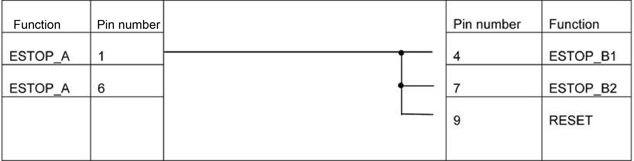
NOTE: If there are no additional emergency stop devices to be added to the system, connect pin 1 to pin 4, and pin 6 to pin 7 to permit the UCC T3 emergency stop switch to function.
NOTE: If the RESET signal is not used, connect pin 6 (E-STOP A) to pin 9 (RESET).
If indicated by the user's risk assessment, a ‘manual reset' button (refer to BS EN ISO13849-1:2008 para. 5.2.2.) should be included in the emergency stop system. A reset switch is required when there is limited visibility of the danger zone from the control position. The reset switch must be positioned outside the danger zone and in a safe position from which it may be determined that no person is within the danger zone before resetting the safety system.
NOTE: Periodically cycle E-STOP buttons, reset push buttons and check for correct position.
The E-STOP buttons should be cycled regularly by operators to ensure correct operation, the frequency of testing having been determined by user risk assessment.
If the reset push button has been fitted, it should be tested regularly by operators to ensure correct operation, the frequency of testing having been determined by user risk assessment.
CAUTION: It is strongly recommended that the CMM manufacturer or retrofitter includes a periodic test of the emergency stop and, if fitted, the associated reset switch, in their maintenance instructions.
E-STOP with reset implementation
There are five methods of implementing the E-STOP circuit.
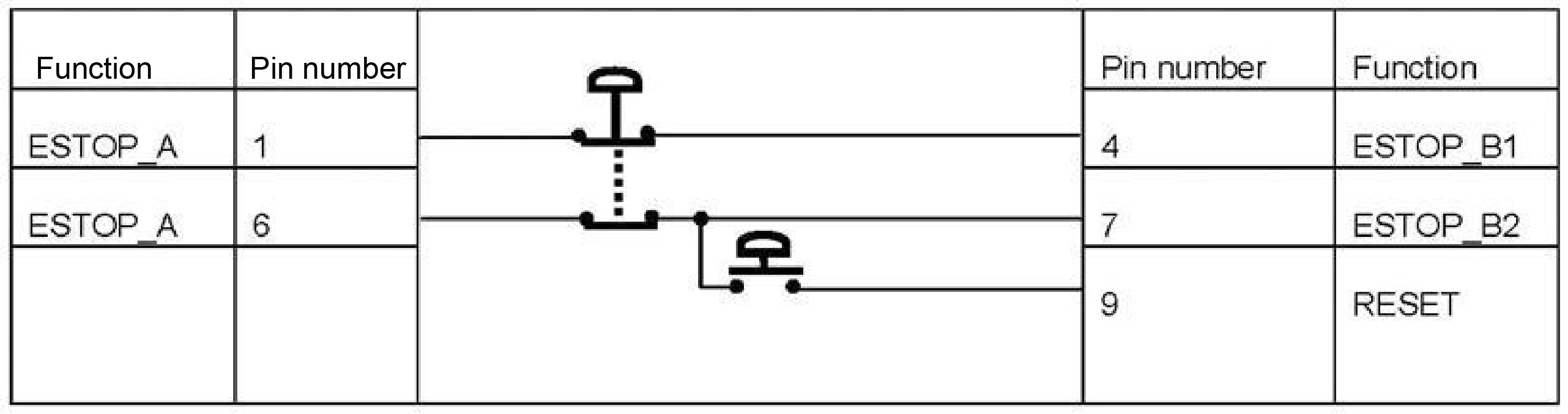
Single pole E-STOP E-STOP button with reset:
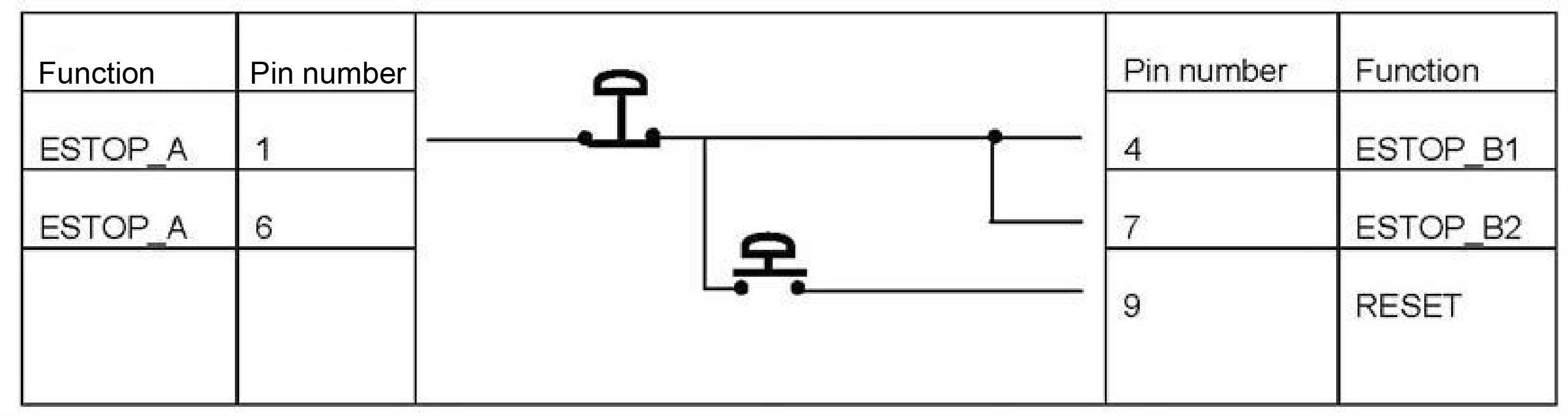
Dual pole E-STOP button with reset:
E-STOP without reset implementation
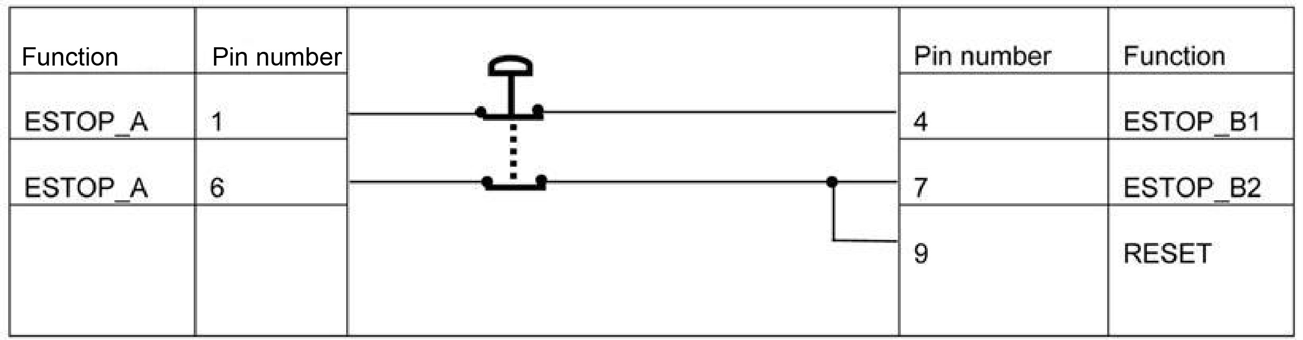
Single pole E-STOP button without reset:
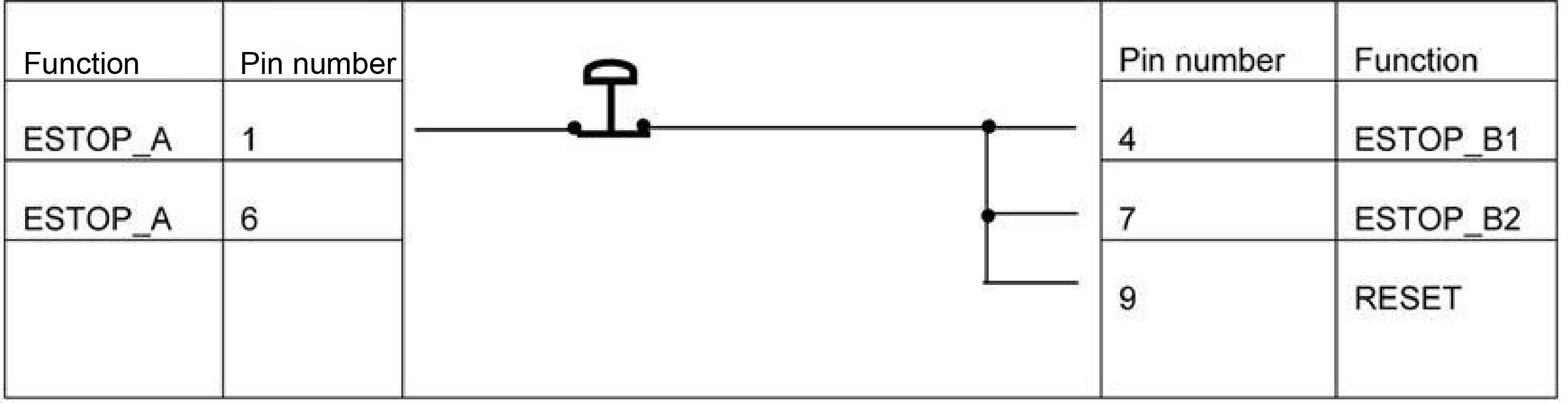
Dual pole E-STOP button without reset:
Bypass plug
E-STOP safety test
The E-STOP buttons should be regularly inspected to ensure that they are in good working order and easily accessible. It should also be tested as follows:
- Ensure that the probe head is free to move in all six directions, using the MCU joystick.
- Hit the emergency stop button. For some systems, the button must then be unlocked by twisting it, as indicated by the arrows on the button.
- Ensure that the probe head cannot be moved, using the MCU joystick.
- Re-engage the servos using the button on the MCU and check that the probe head can now move again.