Navigation
Fitting standard legs to the MRS
Two options are available for mounting the legs to the rail of the MRS. The direct fitting option allows legs to be attached onto the underside of the rail. Using the step-back adaptor option allows legs to be fitted to the back of the rail and provides more measuring volume. Recommended procedures for these two options are detailed in this section.
WARNING: The MRS rail is shipped without the plastic end-caps fitted. Therefore there is a possibility that sharp edges could be exposed.
Direct fitting of legs to the MRS rack
The method for directly fitting legs to the MRS rack is as follows:
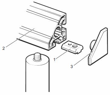
1. Referring to the illustration below, slide the T-nuts (item 1) into the T-nut slot in the underside of the MRS rail (item 2), one T-nut is required for each leg. Ensure that the longer portion of the T-nut is facing away from the end of the rail. The appropriate number of T-nuts should be placed into the slot for the change port or rack device to be used.
2. Once all the T-nuts have been installed in the correct orientation, the plastic end caps (item 3) can be pressed into the rail.
3. Referring to the image below, connect the required number of legs and / or leg extensions (item 1) (up to a maximum of four per leg assembly) and hand-tighten. The MRS leg-to-foot adaptors (item 2) can now be screwed into the bottom of each leg and hand-tightened.
4. Place the MRS legs into the MRS feet (item 3) on the CMM table and adjust the three grubscrews (item 4) so that the legs locate in the MRS feet but are still able to rotate.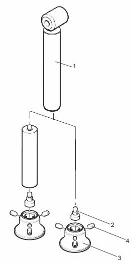
CAUTION: The MRS rack is top heavy. Whilst performing steps 5 and 6, the rail of the MRS must be supported.
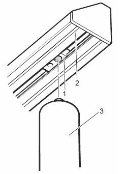
5. Referring to the image below, screw the MRS legs (item 3) into the T-nuts (item 1) at each end of the MRS rack (item 2) and hand-tighten.
6. When the MRS rack is firmly located on the MRS legs, tighten the three grubscrews on each MRS foot using the hexagonal key provided.
Fitting MRS legs with step-back adaptors
The following method describes the attachment of MRS legs with step-back adaptors to the MRS rack:
1. Referring to the image below, insert the asymmetrical T-nut (item 3) for the step-back attachment into the rear T-nut slot of the MRS rail (item 2). Ensure that the longer portion of the T-nut is facing away from the end of the rail.
2. The relevant port or rack mounting T-nuts (item 1) should be installed in the T-nut slot in the underside of the rail. The longer portion of the T-nut should face towards the centre of each respective port.
3. Once all the T-nuts have been installed in the correct orientation, the plastic end caps (item 4) can be pressed into the ends of the MRS.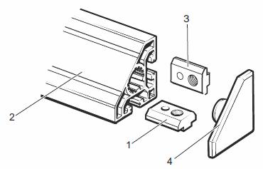
4. Referring to the image in below, insert the M8 screw (item 1) into the step-back adaptor (item 2). Screw the MRS leg (item 3) into the step-back adaptor and hand-tighten. Then screw the required number of leg extensions (up to a maximum of four per leg assembly) into the MRS leg and hand-tighten.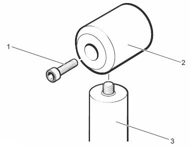
5. Referring to the image below, once the required number of legs or leg extensions have been attached, the MRS leg-to-foot adaptors (item 2) can be screwed into the bottom of each MRS leg assembly (item 1) and hand-tightened.
6. Place the MRS legs into the MRS feet (item 3) on the CMM table. Loosely adjust the three grubscrews (item 4) on each MRS foot so that the legs locate in the MRS feet but are free to rotate.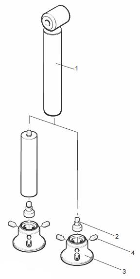
7. If no step back spacer that is required for the RCP and RCP TC-2, position the MRS (item 1) to the step-back adaptor (item 2) and orientate the step-back adaptor so that the M8 screw (item 3) is properly aligned to the MRS T-nut. Screw the step-back adaptor to the MRS using the M8 screw (item 3).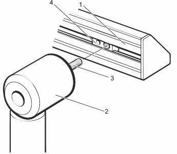
8. If the step back spacer is required, fit the step back spacer onto the step back adaptor (item 2) as shown in the image below. Position the MRS rail (item 1) to the step back spacer (item 4) and orientate the step back spacer and adaptor assembly so that the M8 screw (item 3) is properly aligned to the MRS T-nut (item 5). Screw the step back assembly to the MRS using the M8 screw (item 3)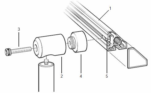
9. Repeat the relevent previous steps for the second MRS leg, hand-tightening the M8 screw on each step-back adaptor.
10. Adjust the position of the rail as required by slackening the M8 screw in the step-back adaptor and sliding the rail into position. Re-tighten the M8 screws using the hexagonal key supplied.
NOTE: Ensure the three grubscrews on each MRS foot are tightened using the hexagonal key provided.