Navigation
SPA3 installation
 Mounting the SPA3
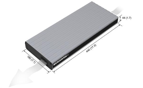
The SPA3 unit draws air from the right hand side when viewed from the front and expels air out of the left hand side. A minimum clearance gap of 10 mm is necessary between the sides of the unit and any potential obstruction. The dimensions shown on the above drawing are in mm (in).
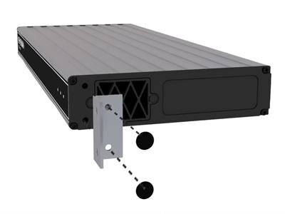
Fitting mounting brackets (optional)
NOTE: The screws supplied with this kit are M5 × 6 mm countersink type.