Navigation
RVP installation
Fitting VPCP and VMCP to the MRS / MRS2 rack
The VPCP and VMCP heated change ports can be fixed to an MRS or MRS2 rack system. It is recommended that they are attached to the MRS / MRS2 rail using the following procedure, where it is assumed that the MRS / MRS2 rack system is correctly installed.
- Insert one of the fixing screws through the VPCP / VMCP.
- Position the VPCP / VMCP underneath the rail and locate the respective T-nut within the rail*.
- Hand tighten the fixing screw into the T-nut and repeat the process for the next fixing screw.
- Position the VPCP / VMCP and tighten both fixing screws using the hexagonal key supplied.
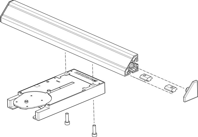
NOTE: The image above shows the VPCP change port but the procedure is the same for the VMCP change port.
* NOTE: T-nuts must be used with the MRS system. However T-nuts and D-nuts are compatible with the MRS2 system.
NOTE: Please refer to the REVO-2 change port system spacing guide (Renishaw part number H-1000-5408) for full details of the recommended spacing for positioning all sensors and artefacts on the MRS / MRS2 rail.
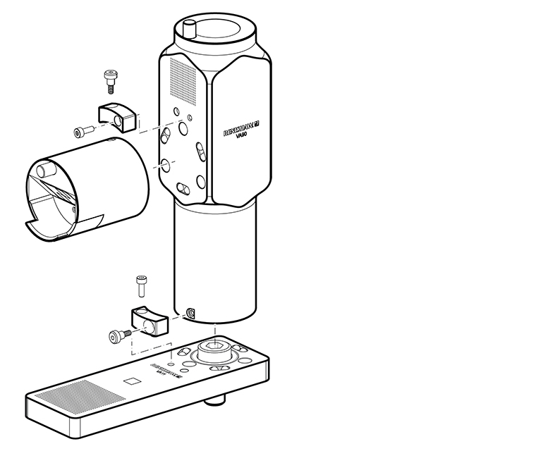
Fixing VA11 calibration artefact and VA90 to CMM
The VA11 calibration artefact is designed to be fixed securely to the bed of the CMM to allow accurate and repeatable calibration of the RVP system components. The diagrams below show how to fix the VA11 to the bed of the CMM.
- Locate an appropriate threaded hole in the bed of the machine.
- Position the artefact plate above the threaded hole.
- Screw the correct cap head bolt through the hole into the threaded hole on the machine. The supplied washer can be used to correctly fit smaller diameter bolts.
- Tighten with a hex wrench.
- Attach the calibration pillar to the kinematic mount. Integral magnets will secure it in place. Polarisation of the magnets will ensure the pillar is fitted in the correct orientation.
- For use with ACM, VA90 can be fitted to the VA11 kinematic mount and the calibration pillar fitted instead to the kinematic mount on the VA90.
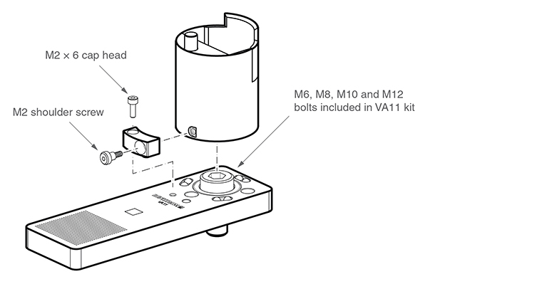
Securing the pillar / VA90
The VA11 pillar and VA90 can optionally be secured to the baseplate or each other using the supplied bracket and screws.
- Fix the VA11 baseplate to the bed of the CMM before securing the pillar or VA90.
- Position the bracket with the curved face towards the pillar.
- Attach the bracket to the baseplate or VA90 using the supplied M2 cap head screw and tighten with a hex wrench.
- Screw the M2 shoulder bolt through the bracket into the pillar or VA90 and tighten with a hex wrench. Ensure the bolt is not overtightened, it should float within the bracket so as not to affect the kinematic location of the pillar or VA90.