Navigation
Touch-trigger probe systems installation
Electrical installation
TP1(S)
The 5-pin DIN socket on the TP1(S) probe provides the connections (shown below) to the probe interface.
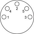
| Pin | Function |
| 1 | LED cathode |
| 2 | Screen |
| 3 | LED anode |
| 4 | Probe circuit |
| 5 | Probe circuit |
TP2 and TP6
Connections to the probe interface are made through the M8 mounting joint.
TP6A
Connections to the probe interface are made through the autojoint.
Fitting a stylus
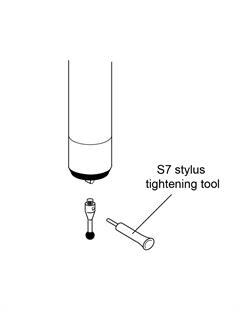
To fit a stylus to a Renishaw touch-trigger probe, insert the correct threaded stylus or stylus adaptor into the stylus mount and tighten the stylus securely using the S7 stylus tool provided. Tightening the stylus by any means other than the stylus tool provided (e.g. spanners, drill bits, etc.) may cause internal damage to the probe mechanism.
NOTE: All stylus joints should be clean and free from dirt or debris.