Navigation
Installation procedure
WARNING: Ensure the PI 7-3 is disconnected from the mains supply during installation.
WARNING: Do not exceed the operation ambient of 50 °C around the unit. Do not install near sources of heat. Forced cooling may be required in final installation.
Rack mounting
The PI 7-3 may be mounted in a 19 inch equipment rack or may be free standing.
To mount the PI 7-3 alone requires 2 × 1/3 blanking panel kits (A-1018-0179).
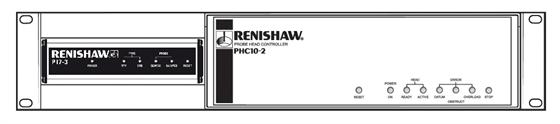
If the PI 7-3 is to be placed next to a PHC10-2 use panel kit A-1018-0173.
System interconnection
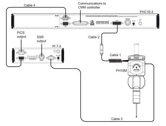
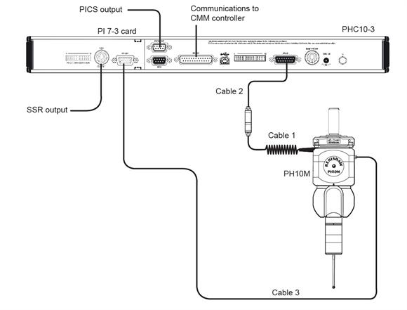
The interconnections for the TP7 system on a PH10M motorised probe head are shown in the following illustrations.
NOTE: The first illustration refers to the external PI 7-3 unit and the second showns information regarding the integral card version of the product. The table gives a list of alternative standard Renishaw cable lengths and part numbers.
Refer to the Renishaw PH10M system installation guide (H-1000-5071) for further information.
| Cable no. | PL no. | Length (m) | Part number | Notes |
| 1 | PL5 PL6 PL12 PL13 | 0.4 to 0.8 0.8 to 1.6 0.1 0.1 to 0.2 | A-1016-7672 A-1016-7673 A-1016-7674 A-1016-7675 | Coiled Coiled Plain Coiled |
| 2 | PLM6 PLM7 PLM8 PLM9 | 6 4 6 4 | A-1016-7564 A-1016-7563 A-1016-7677 A-1016-7678 | Unterminated Unterminated |
| 3 | PL38 PL42 PL56 PL44 PL46 PL45 | 25 15 12 8 3.7 1.8 | A-1016-7625 A-1016-7624 A-1016-7617 A-1016-7627 A-1016-7628 A-1016-7629 | Unterminated Unterminated Unterminated Unterminated Unterminated Unterminated |
| 4 | PL25 | 0.3 | A-1016-0120 |
NOTE: Cables marked ‘unterminated' are supplied with one end prepared but unterminated. The connector parts are supplied for fitting after routing of the cable in the installation.