Navigation
RTP20 operation
WARNING: Safety glasses should be worn and the CMM speed be reduced during initial operation of RTP20.
It is the machine supplier's responsibility to ensure that the user is made aware of any hazards involved in operation, including those mentioned in Renishaw product documentation, and to ensure that adequate guards and safety interlocks are provided.
Preparing RTP20 for use
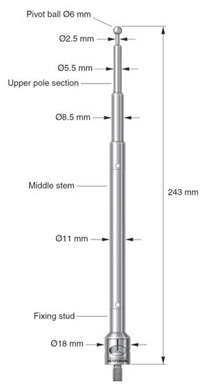
To prepare RTP20 for use, the pivot pole must be correctly fitted to the CMM table to ensure unobstructed operation of the probe head. The pole consists of three sections; a fixing stud, middle stem and upper pole section which has the pivot sphere at its tip. The pole sections must be fitted using the torque tool (supplied) to ensure the pole does not become loose during operation. Various fixing studs are available for different CMM table fixture holes, these are; M6 x 1, M8 x 1.25, M10 x 1.5, 5/16” x UNC and 3/8” x UNC.
Prior to initial use, RTP20 is locked in the A, 0 and B, 0 position to enable the OEM supplied software to define the pivot pole sphere location at eight default positions for RTP20. This is done by calibrating four angles in the A-axis and four angles in the B-axis. Whilst a small degree of misalignment can be accommodated by head/cup geometry, this should be minimised where possible and the first moves should be carried out slowly to confirm clearances.
Using RTP20
To change the orientation of RTP20:
- Use the OEM supplied RTP20 software ‘macro' to send the head to a safety ‘stand-off' position that offers a clear path to the pivot pole sphere.
- From this ‘stand-off' position, send RTP20 to the sphere using the CMM axes to locate and rotate the appropriate left or righthand locking lever of the head to unlock it. The head is then repositioned to engage the RTP20 cup on the pivot pole sphere to index it to the required angle. Once the required angle is reached, the cup is disengaged from the pole sphere and the head is moved to locate and rotate the appropriate locking lever to the re-locked condition.
- RTP20 is then returned to a safety ‘stand-off' position clear of the pivot pole.
- Commence gauging, ensuring that the correct qualification data is recalled for each head position.
To define RTP20 probe head positions:
- Use the OEM supplied RTP20 software ‘macro' to change the orientation of the probe to the next desired position and qualify the stylus tip(s)
- Qualify the stylus tip(s) according to the CMM supplier's instructions
- Repeat the qualification process for all other desired orientations and stylus tips
Periodic re-qualification should be performed under the following circumstances:
- CMM supplier's recommendations, particularly in respect of temperature changes
- At the start of the working day or shift
- After an accidental collision
- After changing any measuring system component (except a prequalified TP20 module)
- If the initial state is unknown or uncertain