| PH10 and PHC10-3 system interconnection diagramsThis section describes a number of PH10 system interconnection and recommended interconnection cables 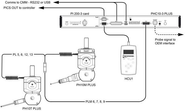
| 1 | Communication connection to CMM controller - RS232 or USB | | 2 | Raw probe signal to OEM interface |
.  | Key | Description |
|---|
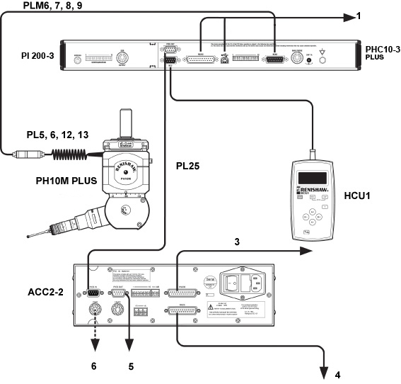
| 1 | Communication connection to CMM controller RS232 or USB | | 3 | Communication to CMM controller | | 4 | Communication to autochange rack | | 5 | PICS output to CMM controller | | 6 | Probe output to CMM controller |
 | Key | Description |
|---|
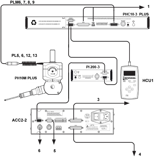
| 1 | Communication connection to CMM controller - RS232 or USB | | 3 | Communication to CMM controller | | 4 | Communication to autochange rack | | 5 | PICS output to CMM controller | | 6 | Raw probe output to CMM contoller |
|