Navigation
PI 200-3 product description
System overview
A small deflection of the stylus tip produces a force which is applied via the stylus module and kinematic coupling to the strain sensing structure housed in the probe body. Electronic processing based on a customised, mixed signal integrated circuit and hybrid microcircuit construction contained within the probe converts the sensor responses to a current proportional to strain. The probe output requires only two wires for transmission to the PI 200-3 interface, enabling the TP200 to use the existing M8 mounting connector system fitted to a wide range of probe heads and extension bars.
In the PI 200-3 interface, the probe current is compared with pre-set reference levels to determine the status of the probe, which may be armed (seated) or triggered. The probe status (SYNC) and the trigger confirmation (HALT) signals are asserted when the appropriate conditions are met.
At power-up, or when a probe is first connected, the PI 200-3 recognises whether the probe is a kinematic switching probe (TP20 / TP6 / TP2 type) or a TP200, and automatically selects the appropriate operating mode.
When using the SCR200 change rack to perform automatic stylus changing, the PI 200-3 inhibits probe triggers and resets the TP200 probe sensor to account for the loading effects of the new stylus assembly on the strain sensors. Collision damage is prevented by an overtravel mechanism and a limit switch in the base of the SCR200. A small displacement will cause the PI 200-3 to assert the SYNC, HALT and STOP signals to stop CMM motion.
Probe status signal (SYNC)
SYNC is the real time PICS trigger signal used to trigger recording of the machine scale coordinates when taking a gauge point. SYNC may also initiate the process of stopping and reversing CMM motion (sometimes called ‘back-off') to the pre-hit point.
When the stylus contacts the workpiece, a change of strain occurs in the sensing structure causing the probe current to increase. SYNC is asserted when the probe current exceeds the trigger reference level. When the stylus backs off from the workpiece, the probe current will fall below the trigger reference level and SYNC will be cleared to the armed state.
The timing relationships for an idealised probe signal are indicated later in this document.
A solid state relay (SSR) output is provided which mimics the PICS-SYNC output for connection to older CMM controllers that require voltage-free contacts to simulate the trigger signal of a kinematic switching probe.
Trigger confirmation signal (HALT)
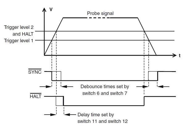
To allow the CMM controller to distinguish between a valid trigger and a spurious trigger caused by vibration or shock, a trigger confirmation signal (HALT) is provided on the PICS port. HALT will be asserted if the probe current remains greater than trigger level 2 for a pre-set delay time, determined by the settings of configuration switches 11 and 12.
Should the probe current fail to reach the trigger level or drop below the reseat level before the delay time has expired, as might be the case for a vibration-induced signal, HALT will not be asserted. The CMM controller may then assume the trigger was spurious and reject the coordinate data.
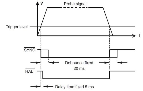
When a kinematic switching probe (TP20, TP6, TP1, TP2) is connected, the HALT delay time is fixed at 5 milliseconds.
SYNC and HALT signal timing for a TP200 gauge point
SYNC and HALT signal timing for a gauge point when a kinematic probe is connected
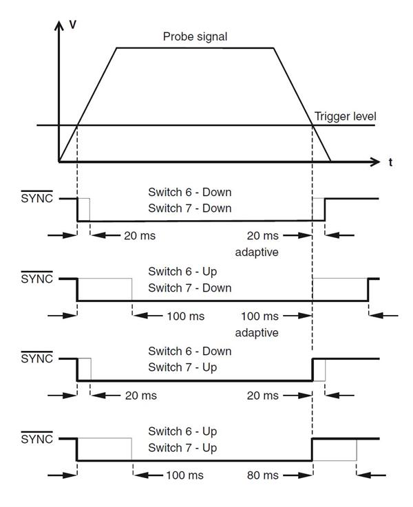
SYNC and HALT debounce
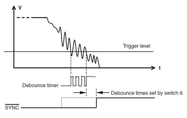
The SYNC and HALT signals are debounced to prevent spurious triggers occurring as a result of CMM or stylus vibration when the stylus makes contact with or leaves the surface of the workpiece. A range of switch selectable timing options is provided to suit the requirements of different types of CMM. Alternatively, the debounce may be switched off to allow greater flexibility for the CMM's controller to manage the PICS signals.
The ‘adaptive' settings ensure that combinations of CMM vibration and large stylus assemblies do not cause a false indication of probe status during the back-off move. It may be seen that the debounce time increases in increments of either 20 milliseconds or 100 milliseconds until the probe signal remains below the trigger level for one complete timing period.
When a kinematic switching probe (TP20, TP6, TP1, TP2) is connected, the debounce times are fixed.
Adaptive debounce
Probe damped signal (PDAMP)
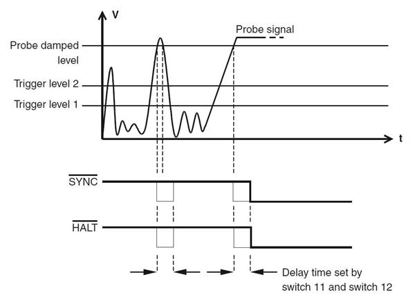
During high-speed position moves (fast traverse), it is necessary to reduce probe sensitivity to prevent vibration causing unwanted triggers. The CMM controller must assert the PDAMP signal on the PICS port, to switch the PI 200-3 into the low sensitivity mode known as ‘probe damped'. In this mode, deflection of the stylus will generate SYNC and HALT simultaneously, but only if the probe signal remains above the damped trigger level for longer than the time delay selected by switches 11 and 12.
Probe damped mode is indicated by an LED on the PI 200-3 front panel.
SYNC and HALT signal timing for a trigger in damped mode
Stylus mass and ambient temperature compensation
In the TP200 probe, a reference strain sensor outside the strain path adjusts the current in the active strain sensors to provide compensation for slow, uniform changes of ambient temperature.
Fine compensation for thermal drift is provided by a system known as ‘autozero' that nulls the sensor amplifiers at a slow rate when the probe is armed. Under the control of the PI 200-3 interface, the autozero automatically switches to a fast rate to reset the probe sensors during a stylus change with the SCR200 change rack or during reorientation of a motorised probe head.
When the probe is in the triggered state, the compensation is switched off. If the stylus remains deflected for longer than ten seconds, drift of the zero reference may occur. The audible warning will sound after this period to indicate that the probe must be reset manually.
RESET button
The RESET button on the front panel selects fast autozero to rapidly null the sensor amplifiers.
This may be necessary when:
- The probe does not arm after manually changing the stylus.
- The audible alarm is sounding a continuous tone to warn that the stylus has been deflected for longer than 10 seconds.
Front panel indicators
PI 200-3 front panel indicators
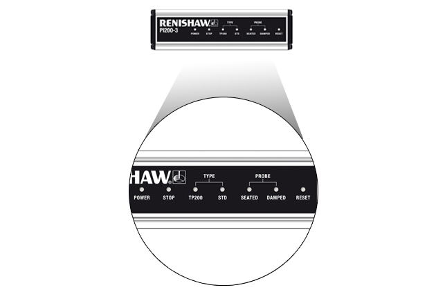
Indicator | Colour | Function |
|---|---|---|
POWER ON | Green | Power on |
STOP | Red | PICS - STOP asserted |
TYPE TP200 | Green | TP200 probe selected |
TYPE STD | Green | Kinematic probe selected |
PROBE SEATED | Green | ON - probe armed (seated) |
PROBE DAMPED | Yellow | PICS - PDAMP asserted |
PHC10-3 PLUS front panel indicators
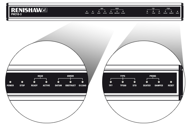
Indicator | Colour | Function |
|---|---|---|
POWER ON | Green | Power on |
STOP | Red | PICS - STOP asserted |
HEAD READY | Green | Head ready |
HEAD ACTIVE | Amber | Head active |
ERROR DATUM | Red | Error datum |
ERROR OBSTRUCT | Red | Error obstruct |
ERROR O/LOAD | Red | Error o/load |
TYPE TP7 | Green | TP7 probe selected |
TYPE TP200 | Green | TP200 probe selected |
TYPE STD | Green | TP20 probe selected |
PROBE SEATED | Green | ON - probe armed (seated) |
PROBE DAMPED | Yellow | PICS - PDAMP asserted |
Audible indicator
The audible indicator has two functions:
The first is to provide a brief indication that a probe trigger has occurred, this function may be disabled by configuration switch 5. The second function is to warn, by a continuous tone, that the stylus has remained deflected for longer than ten seconds. The alarm can be cleared by operation of the RESET button on the front panel.
Rear panel switches and connectors
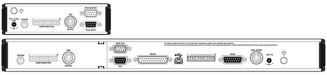
Configuration switches
All switches are hardware controlled and a change to any switch setting is effective immediately.
Configuration switch functions
Switch number | Function | Switch position | Description |
|---|---|---|---|
1 | HALT polarity | UP DOWN | HALT active HIGH HALT active LOW |
2 | Head LED control | UP DOWN | External control via PICS LED mimics SYNC |
3 | STOP disabled | UP DOWN | PI 200-3 ignores PICS - STOP STOP asserts HALT/SYNC |
4 | SYNC polarity | UP DOWN | SYNC HIGH and SSR closes on trigger SYNC LOW and SSR opens on trigger |
5 | Audible indicator | UP DOWN | No beep on trigger Indicator beeps on trigger |
6 | Debounce time |
| Selects SYNC debounce time |
7 | Debounce mode |
| Selects SYNC debounce mode |
8 | Zero debounce | UP DOWN | Sets debounce time <2 ms Debounce set by switches 6 and 7 |
9 | Probe signal filter | UP DOWN | Filter active Filter off |
10 | Trigger level | UP DOWN | Trigger level 2 selected Trigger level 1 selected |
11 | PDAMP / HALT filter delay |
| Coded to select delay time |
12 | PDAMP / HALT filter delay |
| Coded to select delay time Refer to table 3 |
13 | Probe polarity reversal | UP DOWN | Reversed Normal |
Switch 1:
Inverts the polarity of the HALT output.
Switch 2:
Selects control of the LEDOFF output to either internal PI 200-3 control according to the status of SYNC, or sets the output to high impedance for control of the head LED by external switching.
Switch 3:
Sets the PI 200-3's response to STOP when asserted from an external source. When enabled, the PI 200-3 will assert SYNC, HALT and open the SSR relay.
Switch 4:
Inverts the polarity of the SYNC and SSR relay outputs.
Switch 5:
When enabled, a tone will sound for approximately 160 milliseconds when the probe triggers and SYNC is asserted. When disabled, the tone will activate only when the stylus has remained deflected for 10 seconds.
Switches 6 and 7:
These switches select the debounce time and mode of operation.
Switch 8:
Overrides the settings of switches 6 and 7, reducing the trigger and reseat debounce times to less than 2 milliseconds.
Switch 9:
The probe signal filter has a 300 μs time constant to reduce the effects of stylus vibration when the stylus makes contact with the workpiece. Renishaw recommends that this switch is set to the UP position for normal use.
SYNC debounce options
Switch 10:
In operating situations where there is an unusually high level of background vibration, it may be necessary to reduce the sensitivity of the TP200 to avoid false ‘air' triggers. These may occur on some types of CMM when large steel stylus arrangements are used or where the CMM is inadequately isolated from the floor transmission of vibration from nearby machinery or vehicle traffic.
Trigger level 1 | Is the highest sensitivity mode and provides the best measuring performance. |
Trigger level 2 | Reduces the vibration sensitivity from level 1 for a small loss of measuring accuracy. |
Switches 11 and 12:
To prevent a HALT signal (or HALT and SYNC if probe damped mode is set) from being falsely asserted when the probe is subjected to vibration, a time delay filter is applied.
If a collision occurs at fast traverse speed (i.e. a position move), the filter delay time will incur additional CMM overtravel before motion stops. It is important that the CMM motion can stop within the available overtravel, particularly if collisions can occur directly along the main axis of the probe in the +Z direction. To minimise the overtravel in a collision situation, the filter delay time must be set to the shortest possible time that will prevent ‘air' triggers from occurring during fast traverse moves when probe damped mode is asserted.
Switches 11 and 12 are used to select the nominal filter times.
Function of switches 11 and 12:
| Time delay | Switch 11 | Switch 12 |
| 2 ms | DOWN | DOWN |
| 7.5 ms | DOWN | UP |
| 15 ms | UP | DOWN |
| 50 ms | UP | UP |
Switch 13:
| Correct polarity | Down |
| Inverted polarity | UP |
The TP200 probe is polarity sensitive and must be connected to the PI 200-3 such that the centre contact of the M8 connector is positive and the thread is ground (0 V). A reversed polarity connection will cause the POWER and STOP indicators to be illuminated on the front panel.
Sliding the switch to the REV position should allow normal operation. Incorrect setting of the polarity switch should not damage the probe.
When the PI 200-3 is added to the PHC10-3 PLUS, the STOP light will flash at approximately 3 Hz. All PI 200-3 interface LEDs should be OFF.