Navigation
Rear panel description
When the SPA2-2 is delivered it will be in a configurable format and it will be necessary for the motor connection cards to be fitted by the installer prior to applying power.
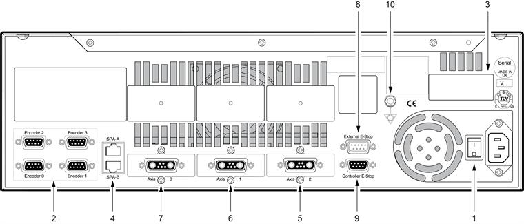
3-axis system rear panel
Key | Description | Refer to section |
|---|---|---|
1 | Power input and ON / OFF switch | - |
2 | Axis 0 - 3 encoder tacho input connectors | Encoder connectors |
3 | Axis 3 motor input connector (optional) | Motor connector |
4 | UCC BI, UCC2 and UCClite communication link connectors | SPA, -A, -B, -C, -D connections |
5 | Axis 2 motor input connector | Motor connector |
6 | Axis 1 motor input connector | Motor connector |
7 | Axis 0 motor input connector | Motor connector |
8 | External emergency stop and reset connector | External emergency stop connection |
9 | UCC BI, UCC2 and UCClite emergency stop connector | UCC2 emergency stop connection |
10 | Earth stud | Electrical requirements |