Navigation
Scale interface (4 × 15W HDD sockets)
UCC BI provides a digital interface for Renishaw digital incremental and absolute encoders (BiSS protocol only), as well as dual signal interface for dual TONiC or Signum systems.
UCC BI can also be used with compatible 3rd party encoders.
Connector details
The port uses a 15-way high-density D-socket, the connections are shown in the table below.
NOTE: If the machine scale is of a different format (e.g. analogue, single-ended) then this will require an external adaptor.

| Pin no. | Function | Function |
|---|---|---|
Incremental | Absolute | |
| 1 | Reserved | Reserved |
| 2 | 0 V scale supply | 0 V scale supply |
| 3 | Error - | Reserved |
| 4 | Reference mark - | Reserved |
| 5 | B signal - | MA - |
| 6 | A signal - | SLO - |
| 7 | +V scale supply | +V scale supply |
| 8 | +V scale supply sense | +V scale supply sense |
| 9 | 0 V scale supply sense | 0 V scale supply sense |
| 10 | /Limit switch Q/ (active low) | Reserved |
| 11 | Error + or /limit switch P/ (active low) | Reserved |
| 12 | Reference mark + | Reserved |
| 13 | B signal + | MA + |
| 14 | A signal + | SLO + |
| 15 | 0 V scale supply (inner screen) | 0 V scale supply (inner screen) |
| Shell | Screen | Screen |
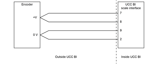
+V scale can be adjusted independently for each scale interface port.
If the scale power sense wires are connected to the respective scale power supply signals at the readhead, the voltage will automatically adjust to maintain +5 V at the readhead.
If the sense wires are open circuit then the voltage can be adjusted through the UCCsuite software. In both cases the scale supply voltage is nominally +5 V and can be adjusted to a maximum of +7 V. The sense and supply signals should be connected as close to the encoder as possible (see diagram below):
The scale inputs support a quadrature waveform with a minimum edge separation of 50 ns, which equates to 20 million counts per second with an ideal waveform.
| Encoder resolution | Maximum move speed |
|---|---|
| 1 µm | 20 m/s |
| 0.1 µm | 2 m/s |
| 50 nm | 1 m/s |
| 1 nm | 0.02 m/s |
UCC BI scale signal interface circuit

UCC BI scale error interface circuit

The UCC BI supports the error signal provided by Renishaw's digital incremental encoders. The UCC BI can also detect tri-state conditions on the A and B signals. If the error signal is not integrated into the connected encoder, then the user should connect pin 3 (Error - ) to pin 7 (+V scale).
UCC BI scale limit switch interface circuit
If scale limit switch signals are integrated into the the encoder being used then the following diagram should be referenced to ensure compatibility with the UCC BI.
