Navigation
PH20 system description
PH20 is a dynamic measuring head and probe system from Renishaw. It is a revolutionary product designed to maximise measurement throughput whilst maintaining high system accuracy for basic entry level measurement systems.
PH20 incorporates Renishaw's long established TP20 probe system into a revolutionary motorised head system to give unprecedented touch-trigger measurement capability. Unlike conventional touch-trigger measurement methods which rely on increased speed of the CMM's 3 axes to measure quickly, PH20 uses head motion to minimise dynamic errors introduced by machine motion at high measurement speeds.
Key features:
- Infinite positioning - not restricted to defined index angles
- Rapid head touches - where the CMM is stationary and the head moves and takes a touch point (UCC T5 systems only)
- Rapid 5-axis moves - synchronised motion of the head and CMM between measurements
Components
- PH20 head
- TCR20 (module change rack with tip datum artefact)
- TP20 stylus modules (excluding extended force)
- UCC T5 or UCC MT5 PH20 CMM controller kit
Connections
The PH20 head and CMM system are operated through the UCCserver which uses I++DME command protocol to communicate between the system application software and the Renishaw controller. The CMM and PH20 head are controlled by the appropriate Renishaw controller, via its standard connections.
System functionality
The PH20 system is compatible with either the UCC T5 or UCC MT5 controller. Both systems offer infinite positioning and 5-axis motion but rapid head-touch measurement is only possible with a UCC T5 PH20 system.
Specification
Standard force module | Medium force module | Low force module | 6-way module | EM1 module | EM2 module | |
|---|---|---|---|---|---|---|
Dimension A (mm) | 21 | 21 | 21 | 25 | 71 | 96 |
Net weight: 810 g
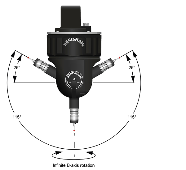
PH20 head axis range
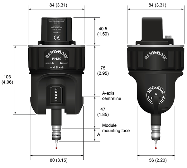
The PH20 head has two rotary axes (A and B) and is normally mounted on the CMM quill to create a 5-axis measuring system. The PH20 B-axis is mounted on the CMM quill and can rotate continuously in both directions. The A-axis, which is orthogonal to the B-axis, has ±115° of travel. The head can only be mounted in the vertical orientation shown below.
TP20 stylus modules
PH20 has an integrated TP20 body that is capable of touch-trigger measurement when used with a suitable stylus module. The probe design utilises the existing range of the TP20 stylus modules, however the TP20 extended force module is not suitable for use on PH20.
Each probe module, which houses the kinematic switching touch sensor mechanism, carries the stylus assembly and provides overtravel in the X, Y and +Z axes (–Z is offered when using the TP20 6-way probe module). Incorporating an M2 stylus mounting, each probe module is compatible with Renishaw's comprehensive range of M2 styli.
Designed to minimise the possibility of probe module misalignment generating a probe ‘seated' signal, the probe module is held in position by a magnetically retained, highly repeatable kinematic coupling. Electrical contact pins conduct the probe sense voltage through the coupling.
Trigger force options
The standard force probe module is suitable for most applications (when used with the recommended stylus range), but sometimes the effects of stylus length and mass, combined with machine acceleration and vibration, can cause the probe to false trigger (these are referred to as ‘false triggers').
To allow the PH20 to be used on co-ordinate measuring machines where acceleration forces or vibration would otherwise result in spurious triggers, a choice of higher force probe modules is available. A low force probe module is also available for measurement of delicate materials. Refer to the applications guide later in this document for information on how to select the correct probe module for your application.
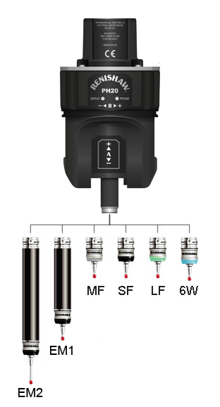
The type of probe modules supplied with your probe will be clearly marked on each probe module's front ring. The probe modules also carry a colour-coded front cap as follows:
- Low force (LF) probe module (green cap)
- Standard force (SF) probe module (black cap)
- Medium force (MF) probe module (grey cap)
- 6-way (6W) probe module (blue cap)
- Extension module 1 standard force (EM1 STD) (black cap)
- Extension module 2 standard force (EM2 STD) (black cap)
NOTE: The extended force module is not suitable for use with the PH20 system.
TP20 module kits
The following TP20 probe module kits are available from your supplier for use with PH20:
TP20 probe module kit (probe module only) | Part number |
|---|---|
Low force probe module | A-1371-0392 |
Standard force probe module | A-1371-0270 |
Medium force probe module | A-1371-0271 |
6-way probe module | A-1371-0419 |
EM1 STD probe module | A-1371-0430 |
EM2 STD probe module | A-1371-0431 |
EM1 STD and EM2 STD probe modules | A-1371-0432 |
Manually mounting / removing the stylus modules to / from PH20
It is not recommended to manually remove and refit a probe module to PH20. If it is absolutely neccessary to manually remove the probe module from PH20 it should only be done in certain orientations. Please see the image below.
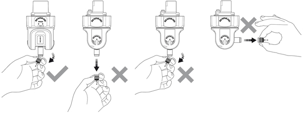
To fit the probe module and stylus onto the probe body, carry out the following procedure:
- Visually examine the mating faces of both the probe module and the probe head for cleanliness; where necessary, clean the mating surfaces using the CK200 cleaning kit (supplied).
- Align the probe module to the PH20 using the reverse of the method used to remove it manually. Ensure the three alignment marks on both the probe module and probe body are correctly aligned, allow the probe module to engage the probe body under magnetic force.
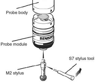
Manually mounting / removing the stylus from the stylus module
To fit a stylus onto the probe module, carry out the following procedure:
NOTE: For advice on both stylus and probe module selection, refer to the applications guide later in this publication.
- Ensuring that you have selected the correct probe module for your given application (see probe module selection later in this guide), screw the threaded end of your chosen stylus into the M2 stylus mount of the probe module and hand-tighten to secure.
- Using the type S7 stylus tools provided, or type S20 spanner if fitting a stylus from the Renishaw GF range, fully hand-tighten the stylus into the stylus mount to achieve the recommended tightening torque of between 0.05 Nm and 0.15 Nm (maximum permissible torque is 0.3 Nm).
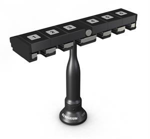
TCR20 rack kit
The TCR20 rack, which can be easily mounted onto a CMM, is designed to securely hold stored probe modules for automatic changing. TCR20 protects stored probe modules from airborne contaminants that may be present within the working environment and also features an integrated tip datum artefact.