Navigation
TP20 probe modules
The Renishaw TP20 probe modules incorporate a kinematic coupling, which ensures highly repeatable stylus tip positioning.
The range of modules comprises 5-way versions with length or trigger force options and a 6-way version.
Probe modules fit directly onto the RTP20 kinematic mount. It is possible to change TP20 modules with different stylus configurations without re-qualification.
Specification
Product compatibility | The TP20 is suitable for use with all Renishaw probe interfaces and probe heads which service the TP2 and TP6 touch-trigger probes. |
|---|---|
Diameter | 13.2 mm |
Length: | |
LF / SF / MF / EF | 38 mm |
EM1 STD | 88 mm |
EM2 STD | 113 mm |
6-way | 42 mm |
Probe module mounting | TP20 kinematic |
Stylus mount | Thread M2 × 0.4 |
Sense directions: | |
LF / SF / MF / EF / EM1 STD / EM2 STD | 5-way (±X, ±Y, +Z) |
6-way | 6-way (±X, ±Y, ±Z) |
Probe module pull-off force | 10 N (1 kgf), 36 ozf maximum |
Sealing | IP30 |
Probe module life | 25,000 changes |
Probe module type and stylus length
Parameter | LF | SF | MF | EF | 6-way | EM1 STD | EM2 STD |
|---|---|---|---|---|---|---|---|
Stylus length | 10 mm | 10 mm | 25 mm | 50 mm | 10 mm | 10 mm | 10 mm |
Trigger force | 0.055 N | 0.08 N | 0.1 N | 0.1 N | 0.14 N | 0.08 N | 0.08 N |
Trigger force | 0.65 N | 0.75 N | 1.9 N | 3.2 N | 1.6 N | 0.75 N | 0.75 N |
Overtravel force | 0.09 N | 0.2 N - 0.3 N | 0.2 N - 0.4 N | 0.2 N - 0.5 N | 0.25 N | 0.2 N - 0.3 N | 0.2 N - 0.3 N |
Overtravel force | 1.1 N | 3.5 N | 7 N | 10 N | 2.5 N | 3.5 N | 3.5 N |
Overtravel force | - | - | - | - | 9 N | - | - |
Overtravel displacement XY* | ±14° | ±14° | ±14° | ±14° | ±14° | ±14° | ±14° |
Overtravel displacement +Z | 3.1 mm | 4 mm | 3.7 mm | 2.4 mm | 4.5 mm | 4 mm | 4 mm |
Overtravel displacement -Z | - | - | - | - | 1.5 mm | - | - |
* The probe module may detach if this value is exceeded
Probe module changing repeatability
Probe module changing method | Repeatability |
|---|---|
Automatic changing | 1 μm |
Manual changing | 2 μm |
Measuring performance
Performance at 10 mm stylus length:
Parameter | LF | SF | MF | EF | 6-way | EM1 STD | EM2 STD |
|---|---|---|---|---|---|---|---|
Unidirectional repeatability* (2σ) | 0.35 μm | 0.35 μm | 0.50 μm | 0.65 μm | 0.8 μm | 0.35 μm | 0.35 m |
2D (XY) form measurement deviation* | ±0.6 μm | ±0.8 μm | ±1 μm | ±2 μm | ±1.5 μm | ±0.8 μm | ±0.8 μm |
* Measured at a trigger speed of 8 mm/s
Test stylus ball diameter 4 mm
The probe module
Each probe module houses the touch-trigger mechanism that carries the stylus assembly. The module provides overtravel in the X, Y and Z axes. The M2 stylus mounting is compatible with Renishaw's comprehensive range of M2 styli.
Electrical contact pins automatically complete the probe circuit.
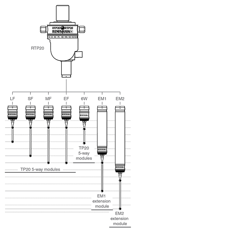
TP20 module selector
Seven versions of the TP20 probe module can be used with the RTP20, they can be identified by the end cap colour.
- Low force (LF) probe module (green cap)
- Standard force (SF) probe module (black cap)
- Medium force (MF) probe module (grey cap)
- Extended force (EF) probe module (brown cap)
- 6-way (6W) probe module (blue cap)
- Extension module 1 standard force (EM1 STD) (black cap)
- Extension module 2 standard force (EM2 STD) (black cap)
Medium and extended force modules are used to overcome the effects of false triggers, caused either by stylus length and mass, or vibration caused by machine acceleration forces.
The low force module permits the measurement of delicate objects.
The EM1 and EM2 extended modules allow access to otherwise inaccessible workpiece features. Both operate using standard force and offer better measuring performance than using long styli with SF, MF, LF or EF modules.
The TP20 6-way senses in the +Z and -Z directions, allowing undercuts to be checked.
Module | Minimum stylus length | Maximum stylus length | Overall reach |
|---|---|---|---|
Low force (LF) | 10 mm (0.39 in) | 30 mm (1.18 in) | 94 mm (3.70 in) |
Standard force (SF) | 10 mm (0.39 in) | 50 mm (1.97 in) | 114 mm (4.49 in) |
Medium force (MF) | 10 mm (0.39 in) | 60 mm (2.36 in) | 124 mm (4.88 in) |
Extended force (EF) | 10 mm (0.39 in) | 60 mm (2.36 in) | 124 mm (4.88 in) |
6-way | 10 mm (0.39 in) | 30 mm (1.18 in) | 98 mm (3.86 in) |
EM1 | 10 mm (0.39 in) | 50 mm (1.97 in) | 143 mm (5.63 in) |
EM2 | 10 mm (0.39 in) | 50 mm (1.97 in) | 168 mm (6.61 in) |
TP20 installation
Assembling the probe module and stylus
- Select the probe module with the correct trigger force rating for the application (see 'TP20 module selector' section).
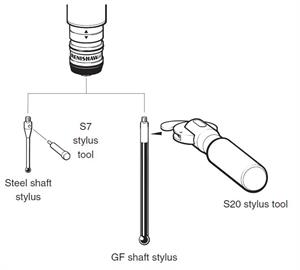
- Fit the stylus to the probe module, first hand tightening then using the S7 stylus tool (supplied) for final tightness. Renishaw GF styli require an S20 spanner. The recommended tightening torque is 0.05 Nm to 0.15 Nm (0.04 lb ft to 0.11 lb ft). Torque must not exceed 0.3 Nm (0.22 lb ft).
Fitting the probe module with stylus on the RTP20
- Examine all mating faces for cleanliness. Where necessary, clean the surfaces with the Renishaw CK200 kit (supplied).
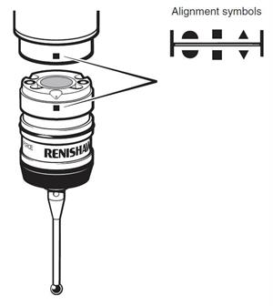
- The TP20 module and kinematic mount are marked with three unique alignment marks. When offering the TP20 up to the probe head, ensure that similar marks are aligned with each other. Allow the TP20 body to engage under magnetic force.