Navigation
UCC BI troubleshooting
UCC BI visual diagnostics
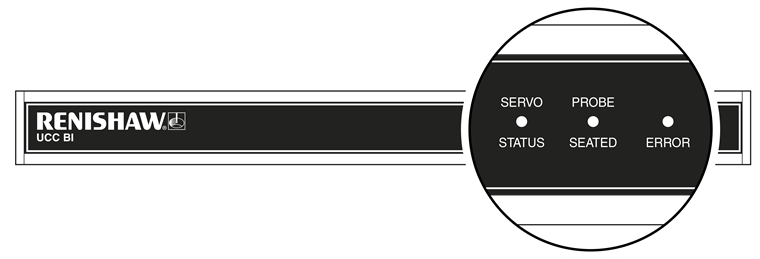
A visual indication of the system status is provided by three LEDs on the front panel, providing assistance in diagnosing and rectifying system faults.
LED status key
| Description |
|---|---|
LED on, displaying green, amber or red | |
Red flash | |
Green flash | |
LED off |
NOTE: The following light patterns apply when using UCCsuite version 5.3 and onwards.
| Servo status | Probe seated | Error | Description |
|---|---|---|---|
No power Amplifier not engaged | |||
Hardware failure | |||
Security failure (fast green flash) | |||
Firmware error (intermittent fast green flash) | |||
** Controller not connected, waiting for download, download failed, device not recognised by UCC firmware or device not recognised by UCC downloadable software | |||
Amplifier not engaged: E-STOP active or amplifier fault | |||
Amplifier not engaged: E-STOP not pressed and amplifier has no fault | |||
Amplifier engaged | |||
Probe seated | |||
Probe not seated |
NOTE: ** A slow flash synchronised with the controller's slow flashing status LED indicates that the UCC BI is correctly connected to the controller and that the controller is waiting for a software download.
Fatal faults
Situations can occur that make it inadvisable or dangerous to continue using the CMM servo system. These are known in UCCsuite as fatal faults.
A list of the main UCC BI related fatal faults is shown below and will be indicated through the user's software (for example MODUS):
- A report of the emergency stop switch being active
- Air pressure is too low
- Crash switch operated, if fitted
- A scale reading failure
- An indicated overspeed (calculated from the rate of change of position)
- Outer limit switch active
- Digital SPA engage relay fault (when a safety relay in the SPA2-2 is detected to be stuck)
- Amp fault (when the SPA2-2 has a fault, which includes emergency stop active)
- PICS_STOP
NOTE: Other faults not classed as fatal can prevent the CMM's operation.
If the fatal fault cannot be resolved, please contact your local CMM support centre who can advise.