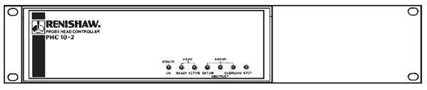
Installation of PHC10-2 ControllerThe PHC10-2 controller can be used in a 19" rack system or as a stand-alone unit. WARNING: Ensure the controller is disconnected from the mains supply during installation. WARNING: Take care not to exceed the operation ambient of 50 °C around the unit. Do not install near sources of heat. Forced cooling may be required in final installation. The dimensions of the controller are as follows: Width: 290 mm (11.42 in) Height: 88 mm (3.46 in) Depth: 220 mm (8.66 in) Weight: 2.8 kg (98.7 oz) NOTE: Use the mounting screws supplied with this equipment. DO NOT replace with longer screws as damage could occur. Stand-alone installationFour self-adhesive rubber feet are supplied with the unit for stand-alone use. Mounting alone in a 19" rackDiagram below shows the PHC10-2 ready for mounting to a 19" rack.
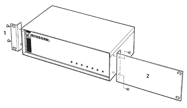
Mounting PHC10-2 in a 19” rack Remove the blanking plugs from the side panels of the PHC10-2 and fit the blanking panel (2) and rack mounting bracket (1) using the screws supplied as shown below.
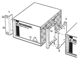
Fitting blanking panel and rack mounting bracket The rack mounting bracket kit (1) is part number A-1018-0124. The blanking panel kit (2) is part number A-1018-0123. Mounting next to an interfaceDiagram below shows the PHC10-2 with a PI200 interface ready for mounting to a 19" rack.
PHC10-2 with PI200 Remove the blanking plugs from the side panels of the PHC10-2. Fit a rack mounting bracket (1) and an enclosure link bracket kit (3) using the screws provided as shown below.
Fitting brackets to the interface The enclosure link bracket kit (3) is part number A-1018-0126. The enclosure link brackets must be fitted in the orientations shown. Fit the brackets to the units before fitting the brackets together. Using the screws provided, fit together the PHC10-2 and the interface. The completed assembly is now ready for fitting to the rack. |