Instructions for usePower up the cabinet using the power switch on the front panel and check the UCC and SPA LEDs are lit. Refer to metrology software documentation for operation instructions. In case of any warnings flagged by software, contact your software provider for assistance. If applicable refer to the Renishaw MCU handbook for details of operation. LED displays for UCC2, UCClite-2 and UCC T3During system file downloading, the power on LED is lit and the error LED is slowly flashing.If the system file download fails then the power on, error and system ready (flashing) LEDs will be lit. In this condition, the UCCs wait for a system restart. Switch the controller off and after approximately 10 seconds switch it on again.
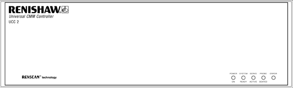
UCC2 visual diagnosticsTo aid troubleshooting of the UCC2 system, five status LEDs are visible through the front panel of the UCC2.
If switch-on is successful the UCC2 proceeds to the initialisation / test sequence. If the initialisation tests fail, then after about 15 seconds three LED configurations are possible, each indicating a different form of failure:
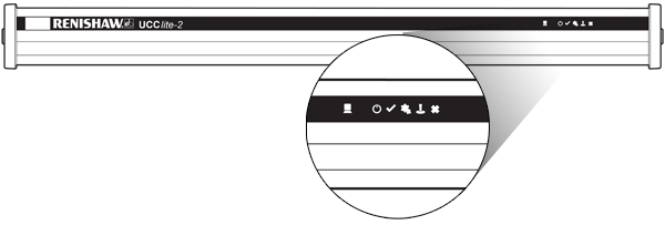
NOTE: The state of all LEDs being off except ‘power on' is the normal switch-on state; it only indicates failure if it remains like this beyond about 15 seconds. Try switching the controller off, waiting about 10 seconds, then turning it on again. If the problem persists, the unit needs attention. If initialisation tests are successful, the power on LED will remain lit and the error LED will start flashing. A slow flash (approximately 0.5 second period) indicates the system is ready for a download. A fast flash (approximately 0.2 second period) indicates the UCC2 is in its IP configuration state. UCClite-2 visual diagnosticsTo aid troubleshooting of the UCClite-2 system, six status LEDs are visible through the front panel of the unit, these are detailed below:
If switch-on is successful the UCClite-2 proceeds to the initialisation / test sequence. If the initialisation tests fail, then after about 15 seconds one of the above error LED configurations will indicate the reason for the failure: NOTE: The state of all LEDs off except ‘power on' is the normal switch on state; it only indicates failure if it remains like this beyond about 15 seconds. Try switching the controller off, waiting about 10 seconds, then turning it on again. If the problem persists, the unit needs attention. If the initialisation tests are successful then the power on LED will remain lit and the error LED will start flashing. The controller is now ready for the system file to be downloaded. UCC T3 visual diagnosticsA visual indication of the system status is provided by four LEDs on the front panel, providing assistance in diagnosing and rectifying system faults.
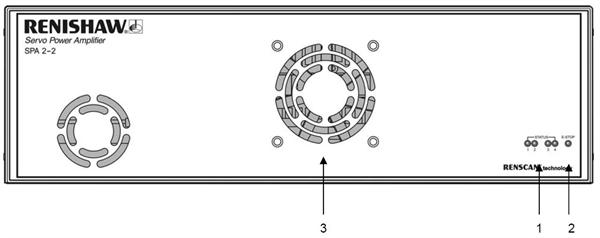
LED displays for SPA2-2 and SPAliteThese LEDs indicate the status of the servo engagement within the SPA2-2 and SPAlite units as shown in the table below:
SPA2-2
SPAlite
The red E-STOP LED indicates if the emergency stop system has been activated. |

 Key:
Key: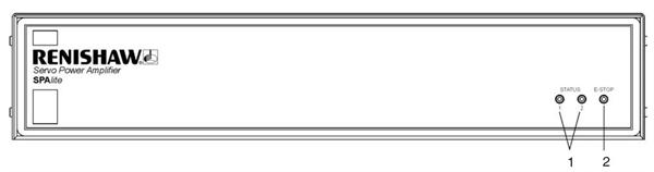 Key:
Key: