Navigation
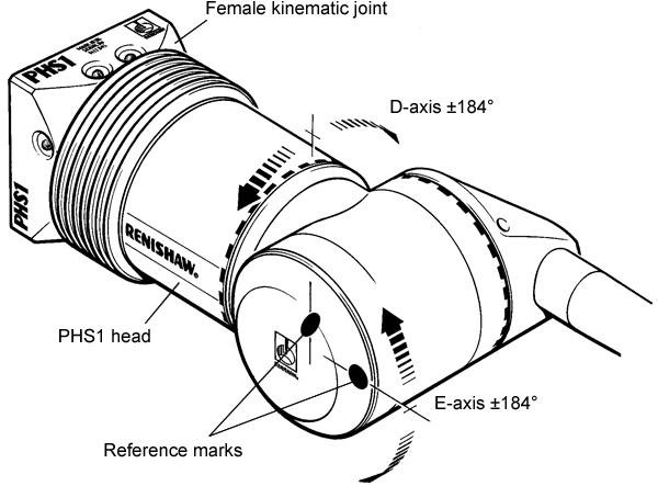
Reference marks
Each axis has a reference mark to enable its zero position to be set. This zero position is nominally at the mid-travel point of the axis - the absolute position of the mark is within ±1.5°.
A microswitch activated by a cam track is used to generate the reference mark; the controller always knows in which direction to travel in order to find the reference point.
To set its zero point, the axis must be driven past the reference mark in a negative direction - see note.
NOTE: A specific procedure must be followed in order for the probe's orientation to be determined. Details of this procedure are given in the PHS1 programmer's guide (Renishaw part number H-1000-6005).
Probe orientation with reference marks nominally at zero:
Axis rotational alignment
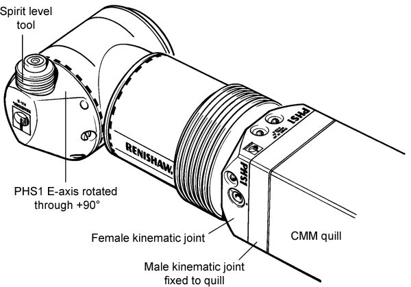
Rotational alignment of the head axes can be found by using the spirit level tool (part number A-2150-1070). The spirit level should be screwed into an HA8 PHS1 M8 arm and the arm mounted onto the head.
The following procedure describes the method of calculating the individual axes offsets.
- Rotate the E-axis through +90°.
- Small adjustments in the D and E-axes should be made until the bubble indicates the head is level.
- Once the head axes have been aligned to the CMM axes, the initial rotation of +90° in the E-axis should be subtracted from the E-axis levelled position.
- These positions are now the angular offsets of each head axis from the datum position.
- These should now be stored in software for that particular head.
Calculation of the individual head axis offsets: