Navigation
System operation
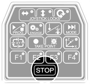
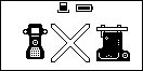
Joystick enable button - MCU5 and MCU W

On the MCU there is a single joystick enable button. The joystick enable button is intended to be used to prevent the accidental movement of the machine. Two actions are required to initiate CMM motion: press joystick enable button and operate the joystick.
NOTE: On the MCUlite-2 the enable buttons are the green arrows in the green boxes.
Joystick and associated button function
All three axis movements are controlled from the one joystick. Moving the joystick left, right, backwards and forwards controls the CMM X and Y movements. The Z-axis is controlled by twisting the joystick clockwise and anti-clockwise (configurable) *.
If a trigger event occurs during joystick operation, the CMM will stop and back away from the surface along the vector that it was travelling. After the back off operation, it is necessary for the joystick to return to its null position for a set period of time before the joystick will permit movement of the CMM. The default value is 0.05 seconds *. The back-off speeds and distances are defined by the UCC configuration settings *.
When in head mode, operation of the joystick can move the axis of the head. Pushing the joystick forwards and backwards will operate the A-axis and twisting the joystick will operate the B-axis.
When in rotary table mode, the W-axis of the table is controlled by the twisting of the joystick.
* These values and configuration settings will have been set by your CMM service provider.
Joystick axis locks buttons

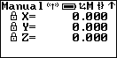
These permit the locking of one or more axes of the CMM, ignoring any joystick deflections for that axis. On each of the axis lock buttons there is an LED indicator that will light red when the respective axis is locked, on the MCU there will also be a padlock symbol next to the respective axis, see figure below. These buttons toggle on or off.
NOTE: If an axis lock is released when the joystick is deflected, that axis is immediately free to move.
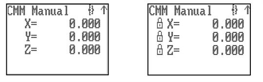
When the MCU is in head mode, the axis locks are applied to the comparable head axes. On the MCU, when the joystick is in head mode and a REVO head is fitted, the left / right axis lock button is used to initialise and cancel ‘SNAP ON'. ‘SNAP ON' is the ability to move the head to the nearest multiple of a defined head angle. These axis locks will only be active during manual (MCU) controlled CMM movements. When the CMM is under DCC operation, all axis locks will be released and re-latched when returning to manual operation.
Probe disable button

The probe disable button gives the CMM user the ability to move the CMM while the probe is triggered or disconnected by disabling the probe trigger signal.
WARNING: When operating in this mode the probe is disabled and therefore probe contact with a surface will NOT stop the CMM. No measured data will be returned to the CMM host computer.
The probe disable function will only work while in manual mode and cannot be applied while in DCC. Press and hold the joystick enable button and then press the probe disable button. The CMM can now be moved irrespective of the probe trigger status. Releasing the joystick enable button cancels the probe disable function. In all modes the application of probe disable is confirmed by the red probe disabled LED being illuminated.
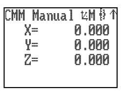
Engage button

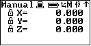
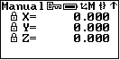
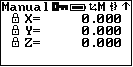
The engage button gives the CMM user the ability to engage or disengage the servos whilst the CMM is in manual mode. This button is configured as a toggle switch and has an associated LED to indicate the servo status. The LED (located within the button) identifies the various operational states and these are as listed below. On the MCU5 and MCU W, a symbol at the top of the LCD screen (shown below) also indicates whether the servos are engaged.
CMM servos are disengaged
LED off – The CMM servos are disengaged
CMM servos engaging
LED amber – The servos are in the process of engaging
CMM servos engaged
LED red – The servos are engaged but the joystick is not enabled
CMM servos engaged and movement is demanded
LED green – The servos are engaged and the joystick is enabled and ready
When REVO or PH20 are fitted, operating the engage switch to disengage the drives puts the REVO or PH20 into heavily damped mode where it will slowly droop due to gravity. The CMM axes will disengage as normal.
Program button - MCU5 and MCU W

This button can be used to request the application software to start or stop a DCC program by a system integrator. The button only gives an event to the application software and is not a state button.
If the button is used to start a program (enter auto mode), the LCD screen will display ‘AUTO', the speed, the controller status and an optional text line from the OEM whilst the program is running. If the button is used to stop a program (enter manual mode) the MCU5 / MCU W returns to the previous mode selected before going into DCC. The LCD screen will then display the normal features for that mode.
Modes button- MCU5 and MCU W

There are six possible MCU5 / MCU W operational modes in addition to the DCC auto mode. Pressing the ‘MODE' button on the MCU keypad changes the MCU operational mode, the current mode is indicated in the top left of the LCD.
NOTE: The modes available to the user of the MCU are configurable. If the mode is not required it can be switched off.
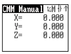
CMM manual mode
This mode is the default on start-up. In manual mode the LCD display will show the tip position of the stylus in the current part co-ordinate system, in either metric or imperial measurements.
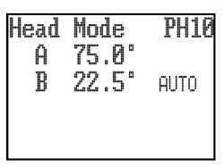
Head mode
Head mode provides the user with control over the Renishaw PH10, PH20 or REVO heads. In this mode the joystick will move either of the motorised head axes. The LCD display will indicate the angle of the two head-rotation axes. For the PH10, the joystick fast / slow button will give jog operation if not pressed or fast sweep operation if pressed. For the REVO, the fast / slow button will control the speed. If no head is fitted then the LCD screen will display ‘None'.
NOTE: To ensure correct operation, the head type must be set correctly within the configuration.ini file.
With the REVO or PH20 head there is an additional facility of ‘SNAP ON'. The use of ‘SNAP ON' is controlled by the use of the left / right axis lock button. Repeated pressing will toggle the facility on and off. ‘SNAP ON' is displayed in text on the LCD display when it is selected. When ‘SNAP ON' is selected the up / down and twist operation of the joystick will move the REVO or PH20 ‘A' and ‘B' axes normally, but after about 1 second of the joystick being returned to its null position the head will automatically move to the nearest multiple of the snap angle. The snap angle is configurable via the configuration file. The maximum snap angle is 7.5° and the minimum is 0.05°.
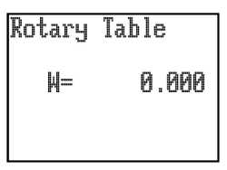
Rotary table mode
This mode provides the user with control over a rotary table if it is connected to the system. Twisting the joystick will cause rotary table movement. The joystick fast / slow button will control fast (pressed) or slow (not pressed) operation. The LCD display will indicate its angle of rotation.
Sticky button mode
The purpose of sticky button mode is to allow the user to alternate between two MCU modes without having to scroll through all of the enabled MCU modes. This feature could be useful when generating a part program using the application software teach utility, where alternating between CMM and head moves is often required.
If the use of sticky button mode has been enabled by your CMM service provider, you will notice that when a MCU mode is selected, the title (e.g. CMM Manual, Head Mode, etc), will be highlighted by displaying it in reverse video (see following example). The highlighted mode title will persist for the time set in the sticky button time delay parameter.
If you want to toggle between two specific modes, this can set by using the following procedure;
a) Using the MCU mode switch, select one of the desired modes, then wait until the mode title returns to a normal video display.
b) Next select the other desired mode and again wait for its mode title to return to normal video.
c) The sticky buttons are now set.
With the REVO or PH20 head there is an additional facility of ‘SNAP ON'. The use of ‘SNAP ON' is controlled by the use of the left / right axis lock button. Repeated pressing will toggle the facility on and off. ‘SNAP ON' is displayed in text on the LCD display when it is selected. When ‘SNAP ON' is selected the up / down and twist operation of the joystick will move the REVO or PH20 ‘A' and ‘B' axes normally, but after about 1 second of the joystick being returned to its null position the head will automatically move to the nearest multiple of the snap angle. The snap angle is configurable via the configuration file. The maximum snap angle is 7.5° and the minimum is 0.05°.
Rotary table mode
This mode provides the user with control over a rotary table if it is connected to the system. Twisting the joystick will cause rotary table movement. The joystick fast / slow button will control fast (pressed) or slow (not pressed) operation. The LCD display will indicate its angle of rotation.
Sticky button mode
The purpose of sticky button mode is to allow the user to alternate between two MCU modes without having to scroll through all of the enabled MCU modes. This feature could be useful when generating a part program using the application software teach utility, where alternating between CMM and head moves is often required.
If the use of sticky button mode has been enabled by your CMM service provider, you will notice that when a MCU mode is selected, the title (e.g. CMM Manual, Head Mode, etc), will be highlighted by displaying it in reverse video (see following example). The highlighted mode title will persist for the time set in the sticky button time delay parameter.
If you want to toggle between two specific modes, this can set by using the following procedure;
a) Using the MCU mode switch, select one of the desired modes, then wait until the mode title returns to a normal video display.
b) Next select the other desired mode and again wait for its mode title to return to normal video.
c) The sticky buttons are now set.
The next time you press the MCU mode button you will return to the original selected mode and, provided you do not press the MCU W mode button before the title has returned to normal video, the next button press will return you to the other selected mode, and so on. Sticky button mode is not permanent, you can still access the other modes. If the MCU W mode button is pressed before the previous mode title has returned to normal video, then the mode becomes unstuck and all the MCU W modes can be scrolled through.
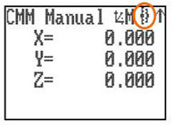
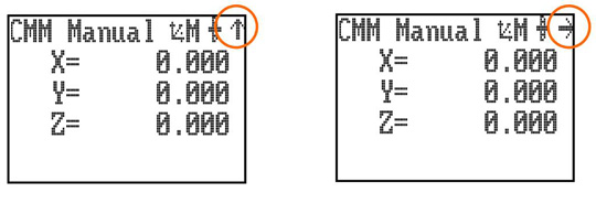
Joystick orientation button - MCU5 and MCU W
The joystick orientation button changes the relative deflection of the joystick to be transposed to the actual axis of the CMM. This allows the user to move freely around any side of the CMM and transpose the joystick orientation such that the machine X and Y-axis correspond to joystick direction of deflection. If any axis lock is asserted and the joystick orientation is changed then the relative axis lock will be transposed also.
An arrow in the top right of the LCD indicates the orientation of the MCU, and pressing the joystick orientation button will enable the user to scroll through the four operational positions. The direction of the arrow is to indicate the +Y axis direction of the machine when the machine co-ordinate system is in force.
NOTE: When switching the system to CMM auto mode, the joystick orientation feature will drop out and then be reasserted when the system is placed into CMM manual mode.
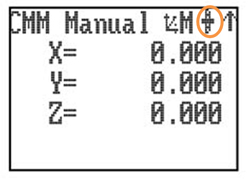
Axis select button - MCU5 and MCU W
The axis select button changes the CMM motion in any one of three different axis systems:
Machine axis (green LED)
In this axis system, the joystick directly controls the machine axes, i.e. a forward deflection of the joystick produces a pure Y+ movement of the CMM. This is the default machine setting when the machine is initialised.
Part axis (red LED)
In this axis system, the joystick controls the machine axes in the current part axis system. i.e. a forward deflection of the joystick produces a movement in the part Y+ direction. This could be a compound of two or three machine axes.
Stylus axis (amber LED)
In this axis system, the joystick controls the machine axes in the axis system of the selected stylus. i.e. a twist (Z) deflection of the joystick produces a movement along the axis of the probe stylus. This could be a compound of two or three machine axes. The stylus axis is a secondary part coordinate system, applicable only to the MCU joystick, and this needs to be updated by the application software to reflect the active stylus axis.
The axis system in which the MCU is moving the CMM is indicated on the LCD by indicating the axis system that is active by a M, P or S, and by a tri-colour LED mounted below the axis select button. Pressing the axis select button will enable the user to scroll through the 3-axis systems.
To change to the required axis system the axis select button must be pressed and held on the desired axis system. This selection is confirmed by pressing the joystick enable switch. Both switches can then be released. This complex change procedure prevents unintentional changing of the axis system which could give unexpected machine movement.
Take point / cancel point

This button is designed to allow the user to record or cancel chosen machine positions. When a program is being generated by the teach and learn method, the user will use the take point button to permit the CMM to record a waypoint and use it in the program. When using the cancel point button it will indicate to the application software that the point just taken (either a touch point or a position generated by the take point button) should be removed from the program. The cancelling process can be repeated many times and the front-end program will use it to delete multiple stored points.
Stylus axis (amber LED)
In this axis system, the joystick controls the machine axes in the axis system of the selected stylus. i.e. a twist (Z) deflection of the joystick produces a movement along the axis of the probe stylus. This could be a compound of two or three machine axes. The stylus axis is a secondary part coordinate system, applicable only to the MCU joystick, and this needs to be updated by the application software to reflect the active stylus axis.
The axis system in which the MCU is moving the CMM is indicated on the LCD by indicating the axis system that is active by a M, P or S, and by a tri-colour LED mounted below the axis select button. Pressing the axis select button will enable the user to scroll through the 3-axis systems.
To change to the required axis system the axis select button must be pressed and held on the desired axis system. This selection is confirmed by pressing the joystick enable switch. Both switches can then be released. This complex change procedure prevents unintentional changing of the axis system which could give unexpected machine movement.
Take point / cancel point
This button is designed to allow the user to record or cancel chosen machine positions. When a program is being generated by the teach and learn method, the user will use the take point button to permit the CMM to record a waypoint and use it in the program. When using the cancel point button it will indicate to the application software that the point just taken (either a touch point or a position generated by the take point button) should be removed from the program. The cancelling process can be repeated many times and the front-end program will use it to delete multiple stored points.
Function buttons

The application software can define the function buttons. Their status can be read at any time and in any mode. These buttons have no effect on the UCC controller as they are solely for the use of the front-end software. The associated keypad LEDs can also be switched on and off at any time. An example of use is that one of the buttons may be used to initiate a circle measurement command when the system is in a manual mode and being used for teach and learn programming.
Keypad STOP button - MCU5 and MCU W
The STOP button gives the operator the ability to rapidly stop the CMM, REVO head and PH20 without disengaging. When the CMM has stopped the system stays in hold state with both the CMM and REVO head engaged.
STOP button - MCU W
Yellow STOP button mounted on the MCU W joystick. When this button is pressed all CMM and motorised head motion is halted.
LCD - MCU5 and MCU W
This LCD screen is context sensitive to the mode and operation of the MCU. Please refer to the relevant operational mode section for further details.
Emergency STOP switch
A red emergency STOP switch is mounted on the MCUlite-2 and MCU5 and on the MCU W cradle which is hard wired to the UCC controller. It complies with EN13850 and when connected to a UCC / SPA the system can comply as either a category 2 or category B E-STOP system as defined in EN954-1:1996 (ISO13849-1:1999). When this switch is operated power to all the CMM axes is removed.
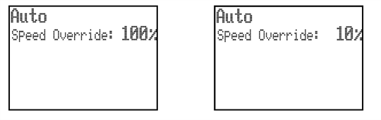
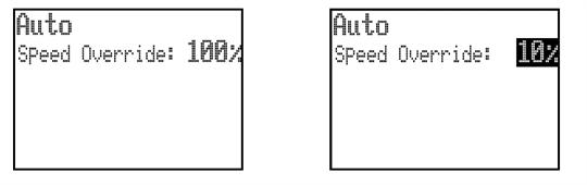
Speed override - MCUlite-2 and MCU5
Controls the machine speed when the CMM is running a program under DCC mode. It will also control the speed of the REVO head and PH20 if fitted. The LCD screen displays a percentage value of the programmed move speed when in DCC operation as shown below. If the speed override is set to less than 10%, the speed percentage shown on the LCD display will flash.
Speed override - MCU W
If the joystick is taken out of range while the CMM is moving in automatic mode the loss of the radio link will not stop the CMM, but if the speed control is changed while the joystick is out of range the following actions are required when the joystick is reconnected.
- If the new demanded speed is lower than the value set before the link was lost then the CMM will immediately slow down to the new speed when the joystick link is reconnected.
- If the new demanded speed is higher than the value set before the link was lost then, when the joystick link is reconnected, the CMM will keep on moving at the old speed but the display of % speed will be reversed (white on black as shown below). The speed will be frozen until the speed control is turned down through the old speed value. The speed control will then again be functional.
Probe disabled LED
The probe disabled LED Indicates the status of the touch probe signal. If the LED if OFF, the probe is in normal operational mode. If the LED is ON (red), the probe is disabled.
MCU enabled LED
The MCU enabled LED Indicates the operational status of the MCU. This LED has two states. If the LED is OFF, the MCU not enabled. If the LED is ON (green), the MCU is enabled.
NOTE: The MCU enabled LED is not illuminated until the joystick is live. If the setting is selected that means the joystick enable button has to be operated, the LED will not illuminate until this is done.
If both the MCU enabled LED is flashing red and green and the probe disabled LED is flashing red, this indicates there is a scale failure on one of the CMM axes.
Specific MCU W screen displays
Wireless communication | |
|---|---|
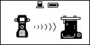
 | Wireless communication is activated |
 | Manual operation, wireless communication - ON, battery - fully charged |
 | Joystick pairing |
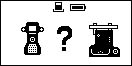 | Pairing lost, (out of range or loss of power to cradle) waiting for the connection |
 | Pairing failed |
Joystick docking | |
|---|---|
 | MCU W joystick is docked in the cradle |
 | Manual operation, MCU W joystick docked, battery fully charged |
The lock | |
|---|---|
 | The key in the MCU W cradle is in the locked position, the MCU W joystick is deactivated and any manipulation of it will not result in the CMM movement |
 | Manual operation, MCU W joystick locked / disabled, battery fully charged |
| Out of range | |
|---|---|
 | The link has been lost due to the MCU W joystick being out of range or the power supply to the MCU W cradle failing |
 | Manual operation, MCU W joystick out of range, battery fully charged |
Battery status | |||
|---|---|---|---|
Battery full | Battery half full | Battery empty | Battery fault / missing |
Power-saving screen back light
After 60 seconds the back light behind the screen turns off if the joystick has not been used
- To activate the screen back light press the joystick enable button