Renishaw’s new VIONiC™ encoder offers unparalleled performance


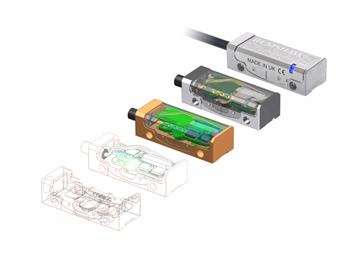
Designed for the world's most demanding motion control applications, the VIONiC series brings together Renishaw's renowned filtering optics with a new custom interpolation and monitoring ASIC (Application-Specific Integrated Circuit) that enhances dynamic signal processing and improves signal stability. Renishaw has created its highest performance incremental encoder system so far, at the same time combining all necessary interpolation and digital signal processing inside the readhead to eliminate the requirement for additional external interfaces.
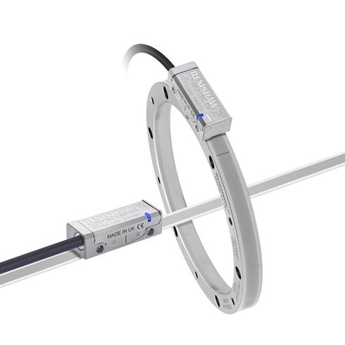
The VIONiC range has been designed to reduce overall system size to the minimum achievable for a high-performance system, whilst delivering class-leading performance in terms of cyclic error, jitter, speed, resolution and accuracy. Customers can choose between two VIONiC readhead variants. The standard VIONiC readhead features a cyclic error of <±30 nm, a range of available resolutions from 5 μm to 20 nm, and speeds beyond 12 m/s. Alternatively for the most demanding performance requirements, customers can select VIONiCplus™ with best-in-class cyclic error to <±10 nm, low jitter of <1.6 nm RMS and resolutions from 100 nm down to 2.5 nm. A comparison of interpolated error values for VIONiC and VIONiCplus encoders is shown in the figure below. High accuracy encoders are essential to minimise velocity ripple, which is important in constant-velocity applications such as laser scanning.
Applications which benefit most from VIONiC are those requiring the highest levels of motion control precision, specifically micro-manufacturing, micro-positioning and precision optics manufacture. This article explores the important role of high-performance encoder systems in these applications.
Micro-manufacturing
Micro-manufacturing is a discipline concerned with the manufacture of small components with dimensions of a few millimetres or less. Micro feature sizes are below those achievable by conventional machine tools. Techniques used in micro-manufacturing are derived from mask-based lithographic processes used in the semi-conductor industry. Modifications to these standard techniques have produced an array of new approaches. Laser micro-machining has gained popularity in recent years, specifically the use of excimer (pulsed) lasers to produce 3D microstructures. The majority of excimer laser systems use a technique known as mask projection and are capable of high feature resolution, fine depth control, excellent reproducibility and the ability to cover large workpiece areas.

In mask projection, the depth profile of microstructural features is controlled by the laser pulse duration, power and beam shape. The beam position on a workpiece is directly controlled by a precision X-Y motion stage. One of the biggest advantages of these systems is their flexibility for a range of micro-engineering tasks. For instance, Synchronised Overlay Scanning (SOS) is a mode of operation whereby the mask and workpiece are moved in unison during the laser machining process. SOS has applications in the printing, semi-conductor and flat panel display (FPD) industries. Since mask projection involves a de-magnification factor, the mask has to travel faster by the same factor and in the opposite direction during synchronised scanning. This is accomplished with high precision motion control via position encoder feedback. The encoder is typically used to determine the position, velocity and acceleration of the workpiece relative to the mask so as to allow the control system to maintain the desired number of laser pulses over the entire exposure area. This requires an encoder with high accuracy due to the effects of error propagation on time-derivatives. As microelectromechanical systems (MEMS) and other micro devices become even smaller and more complex, there will be increasing demand for encoder systems with better accuracy and higher performance.
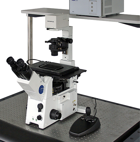
Micro-positioning
Precision optics manufacturing
Precision CNC lens polishing is the final stage of the lens manufacturing process. When polishing spherical or aspherical surfaces using CNC machines, form tools are used that are adapted to the required final lens shape. The tool aperture (polishing surface) is typically large, at twice the lens aperture, but sub-aperture polishing is also possible. Material removal rate during optical polishing depends on the tool pressure and the relative velocity between the tool and workpiece. During the process a polishing suspension is applied, while the polishing tool is traversed across the lens surface through a predetermined computer-controlled path.
Sub-aperture polishing systems are very precise machines that enable the fabrication of shapes that would be too costly to produce using conventional techniques. Sub-aperture polishing involves first bringing the tool into contact with a representative part for a known amount of time in order to characterise the polishing rate. This serves as the basis for the deterministic surface correction of the lens. The next step is to establish the forward removal problem by simulating the tool path as it traverses the optic. The inverse problem is then solved to produce the process parameters required for the desired surface. The solution determines the exact dwell time of the tool at each location, tool pressure and relative tool velocity. CNC lens polishing machines are composed of numerous axes including X, Y and Z axes. An example polishing machine comprises a base with bi-directional Y and X axis linear stages for controlling workpiece position in the X-Y plane. Furthermore, the polishing tool spindle is typically mounted on a rotary axis attached to a vertical slide on the machine frame. The workpiece is also mounted on a separate spindle orthogonal to the tool spindle. Profile inaccuracies for a finished precision lens of <0.5 µm are common. Compact encoders with high-precision and accuracy are required for high-gain positional and velocity feedback control on most of the aforementioned axes. Tool interaction with the workpiece invariably leads to high-frequency disturbances. Expansion of servo-loop bandwidth is required to eliminate errors that cause surface roughness. Inaccuracy in lens polishing tends to lead to the loss of a workpiece and is costly. State-of-the-art encoder solutions are justified in terms of both cost and performance in this industry.
Summary
Renishaw's VIONiC series is the first conventional optical encoder family to deliver the performance advantages of ultra-fine pitch (<4 µm) systems with the additional benefits of better yaw and ride-height tolerance, easier installation, smaller system size, higher speeds, more flexible scale options including longer lengths, better dirt immunity and lower cost. Customer's in micro- and nano- fabrication, precision motion control and other demanding industries can now choose VIONiC encoders for their motion control needs.
For further information on VIONiC systems, please visit www.Renishaw.com/vionic.
Downloads

For more images, videos or information on Renishaw and its products, visit our mediahub.