Navigation
Applications guide
Stylus selection
In the majority of probing applications, to maximise accuracy we recommend that you:
- Keep styli short and stiff
The more the stylus bends or deflects, the lower the accuracy. Probing with the minimum stylus length for your application is recommended and where possible the use of one piece styli is suggested. Probing with excessive styli / extension combinations should therefore be avoided.
- Keep the stylus ball as large as possible
This will ensure maximum ball / stem clearance whilst providing a greater yet rigid effective working length (EWL). Using larger ruby balls also reduces the effect of surface finish of the component being inspected.
EWL is the penetration that can be achieved by any ruby ball before its stem fouls against the feature. Generally, the larger the ball diameter, the greater the EWL (see figure below).
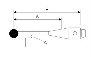
A | Overall working length |
B | EWL |
C | Ball / stem clearance |
EWL can also be affected by assembly tolerances. For this reason, Renishaw styli are assembled to exacting standards in controlled conditions.
Trigger force
Trigger force is the amount of pressure applied by the helical compression spring onto the pivotal plate and bearing points to hold the stylus mount in place.
The trigger force is preset by Renishaw but can be altered for any of the following reasons:
- to permit the use of longer styli on the probe
- to permit the use of heavier styli on the probe
- if the preset trigger force has decreased due to probe use
- if the acceleration of the CMM is causing illegal triggers
All Renishaw's touch-trigger probes have an optimum trigger force setting for general purpose applications as detailed in the table below.
Trigger force:
CMM probes | Stylus length (typical) | Optimum trigger force (preset by Renishaw) | Trigger force range |
TP1(S) | 31 mm (PS1-1R) | 0.15 N | 0.1 N - 0.5 N |
TP2-5 way | 10 mm (PS12R) | 0.07 N - 0.08 N | 0.07 N - 0.15 N |
TP6 / TP6A | 21 mm (PS1-12R) | 0.11 N - 0.13 N | 0.11 N - 0.3 N |
Checking trigger force with the Renishaw gram gauge
1. Ensure that the probe is held firmly in position (preferably on a CMM) and connected to an interface to detect a probe trigger.
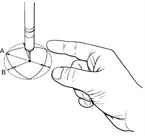
2. Establish the direction of trigger which gives the minimum resistance. The most practical way of doing this is to gently deflect the stylus with a finger, trying different directions. There are three lobes which produce three maximum and three minimum force directions. These can easily be found with a minimum of practice.
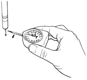
3. Set the gram gauge maximum force indicator to the zero point and place the gram gauge flat on the CMM table. Move the stylus tip to the same height above the surface as the gram gauge lever.
4. Slide the gram gauge slowly sideways so that the flat point on the end of the lever touches the probe stylus ball (ensuring that the probe is deflected in the low force direction). Very slowly continue to move the gram gauge until the probe triggers, at which point stop immediately, back off the gauge and read the maximum force indicator.
5. Repeat this procedure three or four times to ensure consistent results.
Newtons = gf / 100
Trigger force adjustment - TP1(S)
The trigger force of a TP1(S) probe is preset by Renishaw at an optimal performance setting, but can be altered if necessary as follows:
- Remove the probe from the quill of your CMM.
- Insert a 2.5 mm AF Allen key (supplied with every probe) into the centre of the shank until you locate a grub screw.
- Adjust this grub screw to alter the trigger force of the probe:
- Clockwise increases the trigger force
- Anticlockwise decreases the trigger force
Trigger force adjustment - TP2 and TP6
The trigger force of TP2 and TP6 probes is preset by Renishaw at an optimal performance setting, but can be altered if necessary as follows:
- Remove the probe from the probe head on the quill of your CMM.
- Insert a 1.5 mm AF Allen key (supplied with every probe) into the hole in the centre of the M8 thread until you locate a grub screw.
- Adjust this grub screw to alter the trigger force of the probe:
- Clockwise increases the trigger force
- Anticlockwise decreases the trigger force
Trigger force adjustment - TP6A
The trigger force of a TP6A probe is preset by Renishaw at an optimal performance setting, but can be altered if necessary as follows:
- Remove the probe from the probe head on the quill of your CMM.
- Ensure that the cam of the autojoint is in the unlocked position.
- Insert a 1.5 mm AF Allen key (supplied with every probe) through the cam towards the centre of the TP6A until you locate a grub screw.
- Adjust this grub screw to alter the trigger force of the probe:
- Clockwise increases the trigger force
- Anticlockwise decreases the trigger force