Navigation
CMM readhead input connections
The X, Y and Z-axis measuring scale readhead input connectors are high-density 15-way ‘D' sockets.
The X, Y and Z-axis scale readheads of the CMM must be connected to the relevant socket on the rear panel of the UCC MMI enclosure.
Suggestion: Label all readhead connectors to avoid cross connection if removed and replaced in the future.
The three CMM readhead sockets are wired identically, suitable for direct connection to Renishaw RGH2, RGH4 and TONiC ranges of scale.
NOTE: Other manufacturers' readheads and interpolators may require an external adapter to enable them to use the Renishaw standard readhead connector wiring. They may also not produce an error signal to the RS-422 specification.
The UCC MMI supplies the 5.25 Vdc power supply for the readheads. If standard Renishaw readhead cables are used, the recommended cable sizes are 3 m of head cable and 15 m of extension cable, or an equivalent combination. The head cable has 5 times the resistance of the extension cable.
CAUTION: The connection of the cabling should be such that the CMM movements, as reported by the UCC MMI, are of the correct polarity i.e. machine movement in a positive direction along any axis should give positive change of position as reported to the host computer by the UCC MMI controller. Adjust this, if required, by reversing the inputs of the scale readhead signal (change over +A with +B and -A with -B) or switching polarity in UCCassist-2 commissioning software.
These connectors are supplied pre-blanked for use with UCC MMI.
These are RS422 compatible scale inputs for each of the machine axes through the 15-way HDD connectors.
NOTE: If the machine scale is of a different format (e.g. analogue, single ended) then this will require an external adaptor.
Readhead connector (as viewed on the controller rear panel):
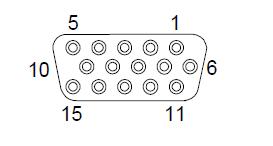
Pin number | Function |
|---|---|
| 1 | External N/C |
| 2 | 0 V supply |
| 3 | - Error |
| 4 | - Reference mark |
| 5 | - B signal |
| 6 | - A signal |
| 7 | +5 V supply |
| 8 | Reserved |
| 9 | Reserved |
| 10 | Limit switch Q* |
| 11 | Limit switch P |
| 12 | + Reference mark |
| 13 | + B signal |
| 14 | + A signal |
| 15 | Inner screen |
Shell | Screen |
* The UCC MMI is capable of supporting both single and dual limit-switch RG22 readheads. The electronic circuits can interface either type without any intervention but the correct type must be set in the machine ini file. If dual limit types are fitted pin 11 functions as the second limit switch.
CMM readhead interface circuit
The signals from a readhead or interpolator should be to EIA specification RS-422.
UCC MMI input circuits for CMM readhead - scale and reference mark inputs:
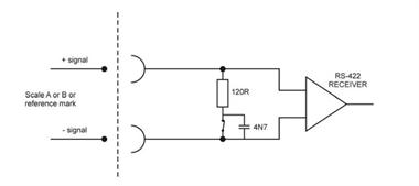
NOTE: If error inputs are not used or the readhead type is RGH24, connect the –Error input to +5 V.
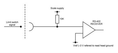
UCC MMI input circuit for CMM readhead - limit switch inputs:
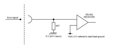
UCC MMI input circuit for CMM readhead – error input:
UCC MMI to CMM measuring scale readhead
The maximum specified cable length is 18 m assuming that individual cable wire cross-sectional area is a minimum of 0.055 mm².
The maximum frequency of any one of the scale readhead quadrature signals, with ideal waveforms and phase displacement, is 12.5 MHz. However, it is recommended that the maximum frequency of any one of the scale readheads should be 10 MHz