Navigation
Establishing a docking position for SM25 and TM25-20 modules
This section describes how to manually position the probe body and module to define the module docking position of the desired port. This process requires very fine movements under CMM joystick control and care must be taken to avoid any collisions of the probe body, module and port.
Eye protection should be work during this procedure and a good level of lighting is recommended to ensure no collisions occur. This procedure is the same when using the FCR25 or the FCR25 TC rack.
1. Latch the port lids open using the triangular plastic inserts provided.
2. Place the SM25 or TM25-20 module in the desired port.
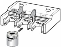
Steps 1 and 2 - latching port lids open and placing module into desired port (n)
3. Ensure the probe head is orientated at an A0 B0 position.
4. Mount the SP25M probe body to the probe head.
5. Inhibit the probe signal through software.
NOTE: Great care is required during the next part of this procedure as there is very little clearance between the probe body and module and the rack port. Carefully observe all movement to ensure that no collisions occur.
6. Using CMM joystick control, position the probe head and SP25M probe body directly above the probe module that has been placed in the rack port.
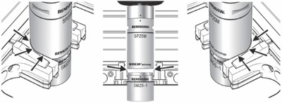
Step 6 onwards - watch for clearances to ensure no collision between parts
7. Slowly lower the probe body towards the probe module ensuring that the XY position of the probe body does not collide with the port.
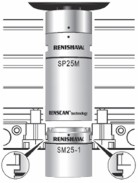
8. Continue to lower the probe body towards the probe module until the magnetic attraction between the kinematic joint makes the module move towards the probe body. The module should move slightly towards the kinematic joint of the probe body without tilting (indicating good XY alignment). If any tilting occurs when the module moves towards the probe body (indicating poor XY alignment) then the probe head and body should be repositioned and the process should be repeated.
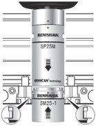
9. Slowly lower the probe body on to the module, stop any movement when the LED on the probe head illuminates. This indicates that an electrical connection is made.
10. Offset the CMM using a DCC movement of 0.75 mm in a –Z direction at a speed of 5 mm/s.
11. Create a datum coordinate system for the module docking position of the port at the following position: [dat_MOD_port(n)].
12. Slowly move the connected probe head, body and module assembly in a –Y direction clear of the port.
13. Remove the module and place back in the port.
14. Enable the probe signal through software (probe signal now armed).
15. Repeat steps 2 to 13 above for all other modules required.