Navigation
Installation procedure - SCR200 rack
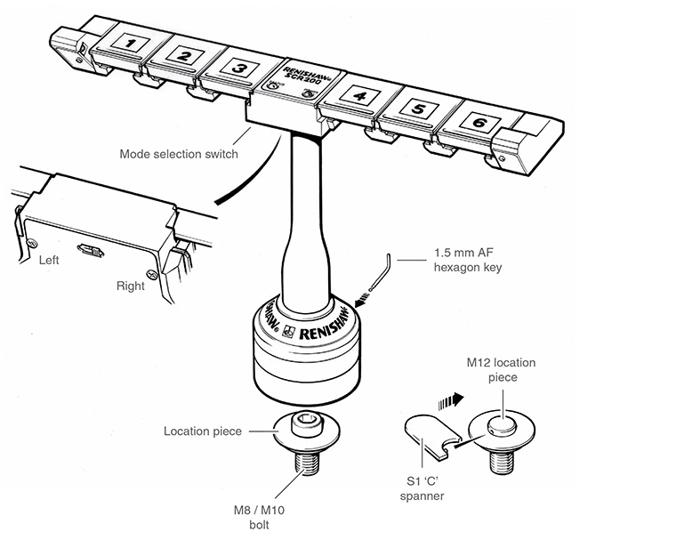
Mounting the SCR200 rack on the CMM
- Place the location piece over a threaded insert at the desired location on the CMM table and screw down using a M8 or M10 bolt and hexagon key (supplied).
- A special location piece with integral bolt is available for M12 inserts (Renishaw part number M-1371-0298). If using this tighten using an S1 ‘C' spanner (supplied with the probe kit).
- Locate the base of the SCR200 rack over the location piece and partially tighten the fixing screw using the 1.5 mm AF hexagon key (supplied).
- Before fully tightening the fixing screw, rotate the rack and align with the CMM axes as described in the following procedure.
NOTES: Your CMM supplier's instructions will indicate the preferred method of alignment. Alignment of the SCR200 with the CMM axes may be essential for some measurement programs or may be desirable for ease of programming.
Aligning the SCR200 rack to the CMM axes
- Align the rack approximately by eye.
- Take points P1 and P2 (see ‘Datuming the SCR200 rack').
- Carefully rotate the rack until the runout between points P1 and P2 is less than 0.2 mm.
- Tighten the fixing screw using the 1.5 mm AF hexagon key (supplied).
Datuming the SCR200 rack
Renishaw recommends that the PS2R stylus (supplied) is used to datum the SCR200 rack.
If a different stylus is used, the length (L) (minimum 20 mm) and the ball radius (R) must be used to calculate offsets.
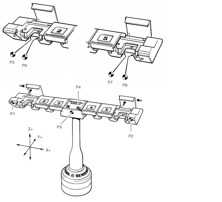
The following instructions assume uncompensated probing points are taken. Therefore, the target positions for stylus module changing are given in absolute machine coordinates. The X, Y, Z axis system refers to the rack axes indicated in the following figure:
IMPORTANT:
The SCR200 rack must NOT be connected to the PI 200-3 interface when performing the datuming procedure.
- Remove the electrical connector before datuming the rack
- Open the lids of ports 1 and 6 and latch in position by sliding towards the centre of the rack
Establishing the docking depth (Y)
- Take point P3
- The docking depth for all ports is: {Y = P3 + R (1 mm) + 14.0 mm}
Establishing the docking height (Z)
- Take point P4 on the top face, ensuring that the point is not taken on the label
- The docking height for all ports is: {Z = P4 – L (20 mm) – R (1 mm) – 18.6 mm}
Establishing the X-axis docking centres for ports 1, 2 and 3 (X1, X2, X3)
- Take points P5 and P6 using the stylus shank to gauge the edges of the module retention plate in port 1
- The docking centre for port 1: {X1 = centre point P5/P6}
- The docking centre for port 2: {X2 = X1 + 30 mm}
- The docking centre for port 3: {X3 = X1 + 60 mm}
Establishing the X-axis docking centres for ports 4, 5 and 6 (X4, X5, X6)
- Take points P7 and P8 using the stylus shank to gauge the edges of the module retention plate in port 6
- The docking centre for port 6 is: {centre point P7/P8 = X6}
- The docking centre for port 4: {X4 = X6 - 60 mm}
- The docking centre for port 5: {X5 = X6 - 30 mm}
Summary of docking target coordinates
- Port 1 = X1, Y, Z
- Port 2 = X2, Y, Z
- Port 3 = X3, Y, Z
- Port 4 = X4, Y, Z
- Port 5 = X5, Y, Z
- Port 6 = X6, Y, Z
After datuming the rack
- Close the lids of ports 1 and 6
- Select the operating mode (Tamper proof ON or OFF, refer to the 'Operating modes' section)
- Connect the cable to the PI 200-3 interface and observe the POWER and STATUS LEDs for correct indication
- Refer to the 'Loading stylus modules into the rack' section
SCR200 electrical connection
Suitable cables for connection of the SCR200 rack to the PI 200-3 interface are available from Renishaw in three standard lengths:
Cable name | Part number | Length |
|---|---|---|
PL63 | A-1016-7630 | 5 m (196.85 in) |
PL64 | A-1016-7631 | 10 m (393.7 in) |
PL65 | A-1016-7632 | 15 m (590.55 in) |
For applications requiring a second rack, a dual rack splitter cable is available.
Cable name | Part number | Length |
|---|---|---|
PL97 | A-1016-7660 | 260 mm (10.24 in) |
NOTE: 2 × standard rack cables of the correct length will be required in addition to the dual SCR200 adaptor cable, which must be installed at the PI 200-3 end.