Navigation
SCR200 rack operation
Operating modes
The SCR200 may be operated in either of two modes depending on the application requirements and whether the SCR200 is accessible in normal operation.
With TAMPER PROOF ON selected, the stylus change cycle is initiated by moving the probe across the face of the Hall sensor, for the rack to detect the presence of the probe before entering a docking port. In this mode, interruption of the light beams alone does not inhibit probe triggering and therefore the probe cannot be accidentally inhibited during normal operation. For example by placing fingers in the light beam or by operating a port lid.
With TAMPER PROOF OFF selected, direct entry to the rack ports is allowed. The light beams detect the probe entering a module docking port and inhibit probe triggers. In this mode faster stylus changing is possible but Renishaw recommend that it is used only in situations where access to the rack is restricted when the CMM is operating automatically.
To select the operating mode
- Remove the electrical connector
- Move the mode selection slide switch (see 'Mounting the SCR200 rack on the CMM') - LEFT for tamper proof ON, RIGHT for tamper proof OFF
- Replace the electrical connector
- Confirm that the POWER and STATUS lamps are indicating the correct mode
Loading stylus modules into the rack
Renishaw recommends that the stylus modules are mounted on the probe body by hand. An automatic stylus change routine is completed prior to tip qualification then the stylus module is loaded into the rack.
The CMM should be used to load the stylus modules into the rack by following the 'Stylus module changing procedure'.
It is possible to load the rack by hand but care must be taken to ensure correct rotational alignment, as there is no warning if a module is incorrectly seated on the probe sensor and gross measurement errors will occur.
Power and status indicators
Two LEDs are located on the top face of the rack:
- POWER - green
- STATUS - red
Power | Status | SCR200 mode |
|---|---|---|
OFF | Flashing for 10 s | Self-test, tamper proof ON |
OFF | Flashing for 5 s | Self-test, tamper proof OFF |
ON | OFF | Rack idle, tamper proof ON |
ON | ON | Rack idle, tamper proof OFF |
ON | Flashing | Stylus changing |
Flashing | Flashing | Self-test failed |
Stylus module changing procedure
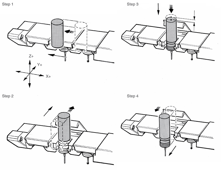
Storing a stylus module - tamper proof ON
Refer to the 'Datuming the SCR200 rack' section for definitions of coordinate X(n), Y, Z.
1. Move to the START coordinate for activating the Hall sensor: {Xs, Ys, Z}, where Xs = X1 + 82 mm and Ys = P3 + R (1 mm) - 7.5 mm.
2. Move along the X- axis to: {Xs - 12 mm} at a minimum speed of 5 mm/s.
3. Move along the X axis to the centre line of the required vacant port (n): {X(n), Ys, Z}.
4. Move along the Y+ axis to the docking target coordinate for port (n): {X(n), Y, Z}
5. Move along the Z+ axis to the release coordinate: {X(n), Y, Zr} where Zr = Z + 3 mm.
6. Move along the Y- axis to a coordinate clear of the port lid: {X(n), Ys, Zr}
Storing a stylus module - tamper proof OFF
Refer to the previous procedure ('Storing a stylus module - tamper proof ON') omitting steps 1 and 2.
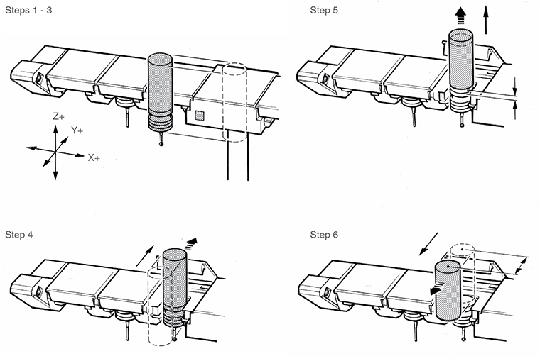
Picking up a stylus module
This procedure is applicable to both operating modes. Refer to the section 'Datuming the SCR200 rack' for definitions of coordinate X(n), Y, Z.
- From the previous port coordinate: {X(n), Ys, Zr}, move along the X axis to the port (n) containing the required stylus module: {X(n), Ys, Zr}
- Move along the Y+ axis to the port centre: {X(n), Y, Zr}
- Move along the Z- axis to the docking target coordinate for port (n): {X(n), Y, Z}
- Move along the Y- axis to a coordinate clear of the port lid: {X(n), Ys, Z}
Proceed with the part measurement program.