Navigation
PH10 System diagrams
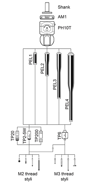
PH10T system diagram
The diagram below shows the range of extensions, probes and styli which can be used in conjunction with the PH10T head.
PH10M and PH10MQ system diagrams
The diagram below shows the range of extensions, probes and styli which can be used in conjunction with the PH10M and PH10MQ heads.
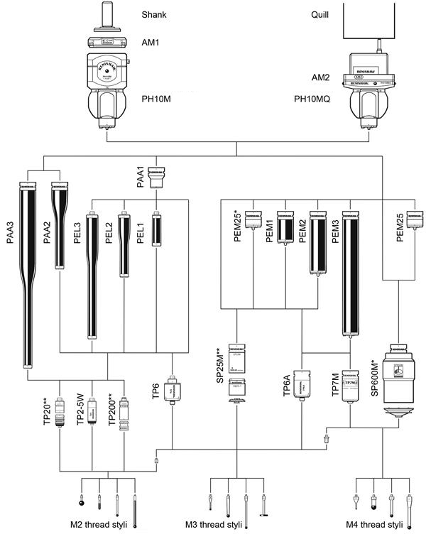
* When using a PH10MQ with SP600M a PEM25 extension bar is required to achieve A = 97.5° or A = 105° in all B-axis positions.
** TP20, TP200 and SP25M are only shown with one module. Other modules are available.