Navigation
Probe operation
The probe has two normal operating states, armed or triggered. The probe should be in the armed state except for the moments when the stylus is deflected against the workpiece.
Probe armed
When the probe is armed (sometimes called ‘seated' or ‘reset'), the following PI 7-3 front panel indicators will be ON:
- POWER ON
- TYPE:
- TP7M when a TP7M is fitted
- STD when a TP2 is fitted
- PROBE: SEATED
Additionally, the probe head LED will be ON.
Probe triggered
Normally, when the stylus touches the workpiece, the SEATED LED on the PI 7-3 front panel will turn OFF. Also, the probe head LED will turn OFF.
The probe should be allowed to remain in the triggered state only for the minimum time necessary to reverse the CMM motion and back-off from the workpiece.
Speed of operation
The TP7M will work at touch speeds between 0.5 mm/s and 40 mm/s.
Use of touch speeds greater than 40 mm/s will result in significantly reduced measuring performance.
Use of touch speeds less than 0.5 mm/s (beware of glancing touches or joystick operations) will result in a possible corruption of the system's trigger and seated reference positions.
Pretravel variation
Pretravel is the distance the probe travels between the stylus touching the surface and a trigger signal being sent to the CMM.
Pretravel is compensated by the CMM computer by probe qualification. However, due to the design of standard probes and the changes in force required to trigger from different directions, there is a small variation in this pretravel. This is called pretravel variation.
On most CMMs using standard software and very long styli (i.e. up to 100 mm), pretravel variation can become a large factor in the probe's total margin of error. It is most evident in inspection routines requiring measurement of form (e.g. following contours or measuring roundness).
Many standard gauging practices, such as measurement of distance between bore centres, are largely unaffected by probe pretravel variation errors.
Stylus selection
To obtain the best performance, apply the following considerations when selecting and fitting a stylus:
- Use the shortest possible stylus length
- Minimise the mass of the stylus by using the types with ceramic or GF stems where possible (refer to the Renishaw stylus catalogue for further information)
- Work with the recommended stylus limits (see graph below in recommended stylus limits)
- Ensure that stylus balls, threads and mating faces are kept clean
- Tighten styli using only the tools provided
- Always qualify the styli at the gauging speed set for the part measurement program - if the speed is changed re-qualify the stylus tip
- Use the largest ball diameter to minimise surface finish effect on measurement
- Whenever possible, use only styli from the M4 range - it is possible to adapt to the M3 or M2 styli, but this will result in reduced measuring accuracy and the user is advised to establish the suitability for the application
Recommended stylus limits
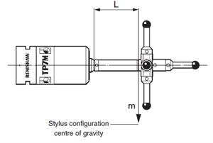
The figure below shows the two parameters of a stylus configuration which, when plotted onto the graph used to determine stylus limits, determine whether or not the stylus is within the specified limits of operation. The stylus parameters shown below are the mass (M) and the length (L) from the stylus mounting to the centre of gravity of the stylus.
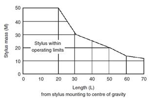
Stylus limits
Graph to determine stylus limits
Trigger level
Under certain conditions, vibration may cause false ‘air' triggers during gauging and it may be necessary to reduce the probe sensitivity. False triggers may occur when large or heavy stylus arrangements are used, or when there is floor transmission from nearby machinery or vehicles:
- Trigger level 1 – the highest sensitivity mode, provides the best measuring accuracy
- Trigger level 2 – lower sensitivity to vibration, but with a small loss of measuring accuracy
The trigger level is selected by switch number 9 on the rear panel of the PI 7-3 interface:
- Level 1 – switch 9 to right
- Level 2 – switch 9 to left
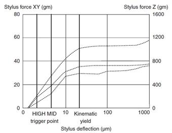
Probing force
This is the force required at the stylus tip to trigger the probe. The TP7M system is designed to trigger at very low forces to minimise distortion of the stylus, workpiece or CMM structure during measurement.
Overtravel forces
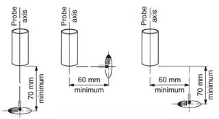
The ability to carry long or heavy stylus confi gurations requires the TP7M to have overtravel forces significantly higher than probing forces. Because these overtravel forces are experienced beyond the trigger point, but within the probe overtravel, measurement accuracy is not affected.For measurement of very delicate components, or use of small styli (Ø0.3 mm or Ø0.5 mm), the overtravel forces may be sufficient to damage the surface or break the stylus. The forces experienced at the stylus tip can be reduced by either extending the stylus tip further away from the probe (as shown below), or minimising the probe overtravel within the touch cycle (as shown below).
Extending the stylus tip from the probe
TP7M force / deflection profiles