Navigation
Reference marks
Each axis must be referenced to enable its zero position to be set. This zero position is nominally at the mid-travel point of the axis - the absolute position of the mark is within ±1.5°.
The PHS-2 has two methods available to determine the zero position, your integrator will setup your system using one of them.
NOTE: A specific procedure must be followed in order for the probe's orientation to be determined. Details of this procedure are given in the PHS programmer's guide (Renishaw part number H-1000-6005).
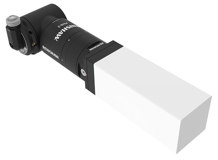
Probe orientation with reference marks nominally at zero:
Axis rotational alignment
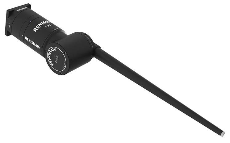
Rotational alignment of the head axes can be found by using the spirit level tool (Renishaw part number A-2150-1070). The spirit level should be screwed into an HA-8 PHS-2 M8 arm and the arm mounted onto the head.
The following procedure describes the method of calculating the individual axes offsets:
- Rotate the E-axis through +90°.
- Small adjustments in the D and E-axes should be made until the bubble indicates the head is level.
- Once the head axes have been aligned to the CMM axes, the initial rotation of +90° in the E-axis should be subtracted from the E-axis levelled position.
- These positions are now the angular offsets of each head axis from the datum position.
- These should now be stored in software for that particular head.
Calculation of the individual head axis offsets: