Navigation
Connectors and signals
The purpose of this chapter is to describe in detail the pin-outs of the connectors mounted at the rear of the UCC2 controller and to show examples of relevant circuit diagrams for the input and output circuits.
The connectors on the rear panel of the UCC2 controller enclosure are shown below:
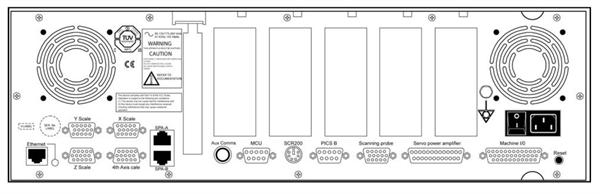
The pin-out of each connector, and its purpose, is described in the following sections.
CMM readhead input connections
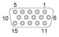
The X, Y, Z and “4th axis” measuring scale readhead input connectors are high density 15-way ‘D' sockets.
The X, Y and Z axis scale readheads of the CMM must be connected to the relevant socket on the rear panel of the UCC2 enclosure.
Similarly the 4th axis scale readhead (dual axis or rotary table capability), if required, must be connected to the socket (marked 4th axis) on the rear panel of the UCC2 enclosure.
Suggestion: Label all readhead connectors to avoid cross connection, if removed and replaced in the future.
The four CMM readhead sockets are wired to the same pin-out, suitable for direct connection to Renishaw RGH22 and RGH24 scale readhead wiring.
NOTE: Other manufacturers' readheads and interpolators may require an external adapter to enable them to use the Renishaw standard readhead connector wiring. They may also not produce an error signal to the RS-422 specification.
The UCC2 supplies a servoed 5 Vdc power supply for the readheads. See 'Electrical power requirements' for details.
If standard Renishaw cables are used, the recommended cable sizes are 3 m of head cable and 15 m of extension cable, or an equivalent combination. That the head cable is 5 times the resistance of the extension cable, e.g. 4 m of head cable and 10 m of extension cable.
Even with the servoed 5 V supply it is still important that the cable resistance is kept to less than 2 ohms.
CAUTION: The connection of the cabling should be such that the CMM's movements, as reported by the UCC2, are of the correct polarity i.e. machine movement in a positive direction along any axis should give positive change of position as reported to the host computer by the UCC2 controller. Adjust this, if required, by reversing the inputs of the scale readhead signal (change over +A with +B and -A with -B).
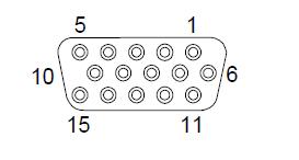
Pin number | Function | Pin number | Function |
|---|---|---|---|
1 | External set up | 9 | 0 V sensing |
2 | 0 V supply from UCC2 | 10 | Limit switch Q* |
3 | - Error | 11 | + Error / limit switch P |
4 | - Reference mark | 12 | + Reference mark |
5 | - B signal | 13 | + B signal |
6 | - A signal | 14 | + A signal |
7 | +5 V supply from UCC2 | 15 | Inner screen |
8 | +5 V sensing | Shell | Screen |
* The UCC2 is capable of supporting both single and dual limit-switch RG22 readheads. The electronic circuits can interface either type without any intervention but the correct type must be set in the machine “ini” file. If dual limit types are fitted pin 11 functions as the second limit switch.
NOTE: The 0 V supply and the 0 V sensing leads are connected together at the readhead. The +5 V supply and +5 V sensing leads are similarly connected at the readhead. It is important that all the cable cores are connected to ensure the voltage drop is compensated for.
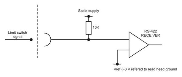
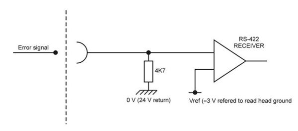
CMM readhead interface circuit
The signals from a readhead or interpolator should be to EIA specification RS-422.
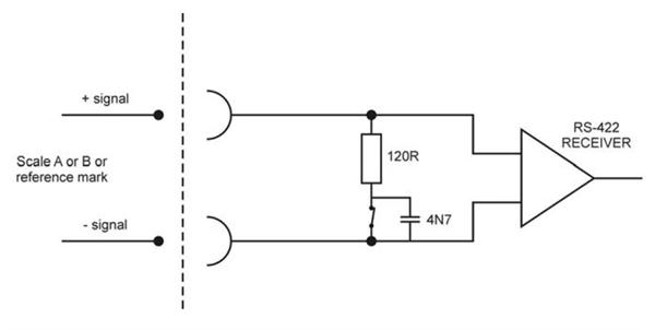
NOTE: If error inputs are not used or the readhead type is RGH24, connect the –Error input to +5 V.
Adjusting readhead supply voltage
It is strongly recommended that the sense lines are connected to the readhead so that the adjustment of the supply voltage, to compensate for cable drop, is automatic. However, there are some circumstances where this is not practical and we have provided a manual method of boosting the supply voltage.
In the .ini file there is a section called ReadHeadPSU which contains three parameters per axis.
These parameters are termination type, enable and voltage.
Termination type - controls the controller readhead circuits to provide either ac termination (0) or dc termination (1) [recommended].
Enable - This is set to 0 as a default which allows the normal automatic voltage servo to operate. If it is set to 1, then the readhead supply voltage can be manually set.
Voltage - This is the manual readhead voltage setting. It is only read when the enable is set to 1 and the allowable range is 5 V to 7.5 V.
NOTE: You must ensure that the voltage at the readhead is within the range 5 V ± 5% (i.e. must not exceed 5.25 V).
SPA2 connector A and B
This is a pair of standard RJ45 connectors that support the high speed communication links to and from the SPA2-2 servo power amplifier. See SPA2-2 installation guide (Renishaw part number H-1000-5234) for details.
UCC2 aux comms
This connector is reserved for future use, no connections should be made to it.
MCU connector
This is a 9-pin 'D' plug suitable for direct connection to the MCU1 / MCU5 or MCUlite joystick unit.
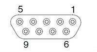
| Pin number | Function | Pin number | Function |
|---|---|---|---|
1 | Ground | 6 | +15 V |
2 | RX_B | 7 | TX_B |
3 | RX_A | 8 | E-STOP_B |
4 | TX_A | 9 | E-STOP_A |
5 | Reserved | Shell | Screen |
SCR200 connector
This is a 6-pin miniature DIN socket suitable for direct connection to the SCR200 stylus change rack.
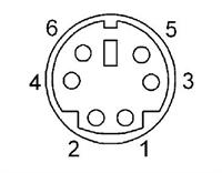
| Pin number | Function | Pin number | Function |
|---|---|---|---|
1 | Remote reset | 5 | 0 V |
2 | Error | 6 | Not connected |
3 | Inhibit | Shell | Screen |
4 | Rack power |
PICS connector
This socket is intended for use with any of the range of Renishaw touch-trigger probes, including the TP200. The connector is a 9-pin miniature 'D' socket, pinout as follows:
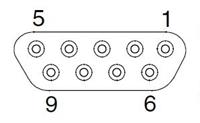
| Pin number | Function | Pin number | Function |
|---|---|---|---|
1 | PICS STOP | 6 | Reserved |
2 | PICS probe power off (PPOFF) | 7 | PICS probe damping (PDAMP) |
3 | 0 V | 8 | PICS LED off (LEDOFF) |
4 | PICS LED anode | 9 | Probe common |
5 | Probe signal | Shell | Screen |
Scanning probe connector
The plug on the cable from the analogue probe connects to the 15-way high-density ‘D' socket on the rear panel of the UCC2.
This socket is intended for use with the Renishaw TP2, TP6, TP20 and TP200 touch-trigger probes and the SP25 and SP600 series of analogue scanning probes.
The pin-out of the socket is as follows:
Pin number | Function | Pin number | Function |
|---|---|---|---|
1 | +5 V supply | 9 | Not connected |
2 | Not connected | 10 | Overtravel |
3 | Probe common | 11 | A signal |
4 | B signal | 12 | 0 V reference |
5 | C signal | 13 | Touch-trigger probe signal |
6 | +12 V supply | 14 | Fixed probe head LED cathode |
7 | -12 V supply | 15 | Fixed probe head LED anode |
8 | Probe identification | Shell | Screen |
Servo power amplifier connector
The UCC2 has the ability to connect a 3rd party servo power amplifier system through this 25-way 'D' socket on its rear panel. A 24 Vdc supply is also provided by the UCC2 through this connector to energise the CMM status switch.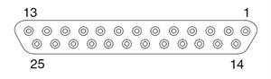
Pin number | Function | Description | Refer to section |
|---|---|---|---|
1 | +24 Vdc | Supply provided for use with CMM status switches | "+24 V dc" |
2 | Contactor (active low) | Output signal to control motor contactor (active low) | "Contactor" |
3 | E-STOP_C | E-STOP system - reset signal | "ESTOP_C" |
4 | Enable amps (active low) | Command to SPA to enable amplifiers (active low) | "Enable amps" |
5 | Contactor (active high) | Output signal to control motor contactor (active high) | "Contactor" |
6 | E-STOP_A | E-STOP signal from MCU1 / joystick | "E-STOP_A and E-STOP_B" |
7 | E-STOP_B | E-STOP signal from MCU1 / joystick | "E-STOP_A and E-STOP_B" |
8 | -X command | Differential output to CMM X drive motor | "Axis command signals" |
9 | X command | Differential output to CMM X drive motor | "Axis command signals" |
10 | -Y command | Differential output to CMM Y drive motor | "Axis command signals" |
11 | Y command | Differential output to CMM Y drive motor | "Axis command signals" |
12 | -Z command | Differential output to CMM Z drive motor | "Axis command signals" |
13 | Z command | Differential output to CMM Z drive motor | "Axis command signals" |
14 | -4th axis command | Differential output to CMM 4th axis drive motor | "Axis command signals" |
15 | 4th axis command | Differential output to CMM 4th axis drive motor | "Axis command signals" |
16 | Command common | Reference line for power amplifiers | "Command common" |
17 | Reserved |
| "Reserved" |
18 | Reserved |
| "Reserved" |
19 | Reserved |
| "Reserved" |
20 | Reserved |
| "Reserved" |
21 | Enable amps (active high) | Command to SPA to enable amplifiers (active high) | "Enable amps" |
22 | Contactor feedback | Confirmation of contactor operation | "Contactor feedback" |
23 | Amps OK | Confirmation from the servo amplifiers that they are ready | "AMPs OK" |
24 | E-STOP tripped | Indication from the SPA that the ESTOP signal is asserted | "E-STOP tripped" |
25 | 24 V return | Common reference line for supply and contactor signals | "0 V (24 V return)" |
Shell | Screen |
+24 Vdc
+24 Vdc supply provided for the use of contactors, relays and other motor control circuits. Current limit 1 A.
Contactor
This command is issued by the UCC2, to the SPA, to engage the motor contactor. This output signal can drive the contactor directly providing its current consumption is within the output specification. This output signal is available in both an active low on pin 2 and an active high on pin 5.
E-STOP_C
This is the E-STOP reset line from the servo power amplifier. It is made available to the UCC2 plug in daughter-card slots for incorporation by products that need to be aware or pass on this signal's status. It is part of the “category 2” E-STOP system supported by the UCC2 and SPA2 controller system.
Enable amps
This is a command from the UCC2 to the SPA requesting it to enable its amplifiers. This output signal is provided as both an active low signal on pin 4 and as an active high signal on pin 21.
E-STOP_A and E-STOP_B
These are the connections from the SPA E-STOP system to the joystick / MCU mounted emergency stop switch. E-STOP_A is the high end and E-STOP_B is the return. The E-STOP_B signal is also made available to the UCC2 plug in daughter-card slots for incorporation by products that need to be aware or pass on this signal's status. A rotary table is a good example of where it needs to be incorporated as part of the E-STOP system.
Axis command signals
These outputs (pins 8 to 15) are the velocity demand signals for each axis from the UCC2 to the servo power amplifiers. They vary over the range +10 V to –10 V.
Command common
An analogue reference zero is available to the servo power amplifiers but this signal is not used by our SPA1 and SPA2 amplifiers although some third party units do require this reference. It is important that this is not used as a 0 V return for digital signals because this will inject noise into the velocity demands. This pin (16) should be left open circuit if not required.
Reserved
These pins (17 to 20) have high-speed serial communication driver / receivers connected to them, they are intended for future development. It is important that these pins should be left open circuit.
Contactor feedback
This is a confirmation signal from the motor contactor to the UCC2 that is has successfully operated and the motors are now engaged. This signal was on the I/O connector (pin 24) for the UCC1 and is still available on that connector on the UCC2 for backwards compatibility reasons.
AMPs OK
This is a confirmation signal (pin 23) from the servo amplifiers that they on and ready. It is produced as a response to the Enable Amps command. This signal was on the I/O connector (pin 19) for the UCC1 and is still available on that connector on the UCC2 for backwards compatibility reasons.
E-STOP tripped
This input (pin 24) is used to inform the UCC2 of the CMM ‘Emergency Stop' condition (E-STOP). If the input pin is pulled down to 0 V (24 V return) the UCC2 will assume that there is no emergency stop active and allow the servo motors to be energised. This input is also on the I/O connector pin 21.
If the input pin is open-circuit or near +24 V the UCC2 will assume that the emergency stop is active and will disable all motors and inform the host computer of the event.
NOTE: No motor can be enabled while this input is high or open-circuit.
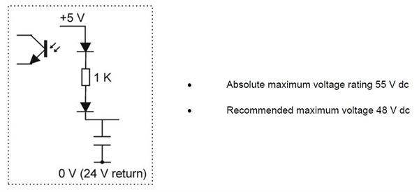
0 V (24 V return)
This is the 0 V reference connection for all the digital and switching signals, unless otherwise stated the 0 V connections from all external devices should be connected to this line. This signal line is available on pin 25 on the SPA connector and pins 37 and 44 of the I/O connector. It is taken to a star point within the UCC2 controller where it is connected to protective ground, cable screens and all the internal supply 0 V lines. The star point must be the only point that these different 0 V and ground connections are made.
Machine I/O connector
The plug on the cable from the CMM connects to the 44 way miniature (high density) socket on the rear of the panel of the UCC2.
The input/output (I/O) signals to/from the UCC2 controller are:
- Air solenoid output
- X, Y and Z brake outputs
- Emergency stop switch
- Machine air pressure switch
- Crash switch
- Contactor feedback
- X+ and X-, Y+ and Y-, 4th axis- and 4th axis+, Z+ and Z- inner and outer limit switches of the CMM
- General purpose outputs and inputs
- 24 Vdc supply and return
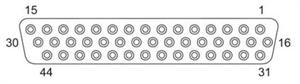
Pin number | Function | Description | Refer to section |
|---|---|---|---|
1 | +24 Vdc | Supply provided for use on CMM switches | "+24 Vdc" |
2 | Air solenoid | CMM air solenoid output signal | "Air solenoid" |
3 | X brake | CMM X brake output signal | "X, Y, Z brake" |
4 | Y brake | CMM Y brake output signal | "X, Y, Z brake" |
5 | Z brake | CMM Z brake output signal | "X, Y, Z brake" |
6 | Output 0 | General purpose output signal | "UCC2 general purpose outputs" |
7 | Output 1 | General purpose output signal | "UCC2 general purpose outputs" |
8 | Output 2 | General purpose output signal | "UCC2 general purpose outputs" |
9 | Output 3 | General purpose output signal | "UCC2 general purpose outputs" |
10 | Output 4 | General purpose output signal | "UCC2 general purpose outputs" |
11 | Output 5 | General purpose output signal | "UCC2 general purpose outputs" |
12 | Output 6 | General purpose output signal | "UCC2 general purpose outputs" |
13 | Input 0 | General purpose input signal | "UCC2 general purpose inputs" |
14 | Input 1 | General purpose input signal | "UCC2 general purpose inputs" |
15 | Input 2 | General purpose input signal | "UCC2 general purpose inputs" |
16 | Input 3 | General purpose input signal | "UCC2 general purpose inputs" |
17 | Input 4 | General purpose input signal | "UCC2 general purpose inputs" |
18 | Input 5 | General purpose input signal | "UCC2 general purpose inputs" |
19 | Amplifier OK | "Amplifier OK input" | |
20 | CMM declutch | "CMM declutch" | |
21 | E-STOP tripped | "ESTOP tripped" | |
22 | Air pressure | Machine air pressure switch input | "Air pressure switch" |
23 | Crash | Crash detector switch input | "Crash switch" |
24 | Contactor feedback | Contactor input signal | "Contactor feedback" |
25 | X axis outer limit | CMM X axis limit switch input | "Limit switches" |
26 | -X axis outer limit | CMM X axis limit switch input | "Limit switches" |
27 | Y axis outer limit | CMM Y axis limit switch input | "Limit switches" |
28 | -Y axis outer limit | CMM Y axis limit switch input | "Limit switches" |
29 | Z axis outer limit | CMM Z axis limit switch input | "Limit switches" |
30 | -Z axis outer limit | CMM Z axis limit switch input | "Limit switches" |
31 | X axis inner limit | CMM X axis limit switch input | "Limit switches" |
32 | -X axis inner limit | CMM X axis limit switch input | "Limit switches" |
33 | Y axis inner limit | CMM Y axis limit switch input | "Limit switches" |
34 | -Y axis inner limit | CMM Y axis limit switch input | "Limit switches" |
35 | Z axis inner limit | CMM Z axis limit switch input | "Limit switches" |
36 | -Z axis inner limit | CMM Z axis limit switch input | "Limit switches" |
37 | 24 V return (0 V) | Common reference line for input and output signals | |
38 | 4th axis brake | Reserved for future use | |
39 | +4th axis outer limit | CMM 4th axis limit switch input | "Limit switches" |
40 | -4th axis outer limit | CMM 4th axis limit switch input | "Limit switches" |
41 | +4th axis inner limit | CMM 4th axis limit switch input | "Limit switches" |
42 | -4th axis inner limit | CMM 4th axis limit switch input | "Limit switches" |
43 | Reserved | Reserved for future use | "Air pressure switch" |
44 | 24 V return (0 V) | Common reference line for input and output signals | "24 V return" |
Shell | Screen |
+24 Vdc
+24 Vdc supply provided for the use of contactors, relays and other motor control circuits. Current limit 1 A.
UCC2 general purpose outputs
These 7 transistor output signals (pins 6 to 12) are switched on and off by commands from the host computer (See the UCC programmers guide, command number 318). The outputs are active low.
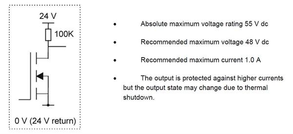 When the output is not activated the transistor is not switched on and the output pin is lightly pulled high (+24 V) via a 100K resistor. When the output is activated, by sending a ‘1' to the relevant control bit the transistor will turn on, pulling the output pin down to the 0 V (24 V return) line.
UCC2 general purpose inputs
These 6 opto-isolated LED inputs (pins 13 to 18) to the UCC2 can be used to send signals from the CMM to the CMM host computer via the UCC2 (see the UCC programmers guide, command number 279). Pulling an input pin low, towards the 0 V (24 V return line) will cause the controller to return a ‘0' in reply to the read command.
Air solenoid
This output signal (pin 2) is used to activate the CMM main air supply solenoid (if fitted). The output becomes active as soon as a downloadable is sent to the UCC2 controller. The output is active low.
X, Y and Z brakes
These outputs (pins 3,4 and 5) are used to disengage the CMM axis brakes (if fitted). The outputs become active as soon as the CMM servos are engaged. During the commissioning process it is possible to invert the output from the brake connections from active low to an active high.Amplifier OK input
This signal (pin 19) is produced by the servo power amplifier to inform the connected UCC2 controller that ALL the servo power amplifiers have been successfully enabled, it is an active low signal i.e. pulled to 0 V (+24 return) to indicate success. This signal is a response to an active ‘amp control' signal from the controller. This signal is also available on the SPA connector pin 23.CMM declutch
This input on pin 20 should normally be pulled down to the 0 V return line, to signal to the controller that the CMM's drives are mechanically connected to the moving elements of the machine, i.e. in their normal condition. The input should be open circuit, or held high, when a CMM has been temporarily ‘de-clutched' from its drive motors to allow manual positioning. The servo system will not drive the motors in this condition and will resume control at the machine‘s position when he signal again goes low.E-STOP tripped
This input (pin 21) is used to inform the UCC2 of the CMM ‘emergency stop' condition (E-STOP). This signal is also available on the SPA connector pin 24. If the input pin is pulled down to the 24 V return line, the UCC2 will assume that there is no emergency stop active and will allow the servo motors to be energised. If the input pin is open-circuit or near +24 V the UCC2 will assume that the emergency stop is active and will disable all motors, and inform the host computer of the event.
NOTE: No motor can be enabled while this input is high or open-circuit.
Air pressure switch
The low air pressure signal should be connected to a suitable air pressure switch. This input is monitored by the controller and when activated will remove power from the motors causing a system fatal fault. During commisioning process it is possible to invert this signal from an active low to an active high. If this capability is not required for intergration to the system then it should be connected to the 0 V.
Crash switch
This input signal (pin 23) is used to stop the CMM movement if there is a collision involving parts of the CMM and probe system, as detected by a switching mechanism.The crash switch should pull the input down to 0V return line. If the input is not pulled down, the UCC2 will disable all motors, and inform the CMM's host computer of this state. During commisioning process it is possible to invert this signal from an active low to an active high.
Contactor feedback
This input signal (pin 24) is used by the UCC2 to monitor the operation of the axes drive motors control contactor. This signal is also available on the SPA connector pin 5.When the contactor is energised (drive motors enabled), this signal should be pulled down to the 24 V return line to indicate that motor power is available.
If the UCC2 has turned on the ‘contactor' output (servo power amplifier socket, pin 2) and the signal on pin 24 indicates that the contactor has not operated, after a short delay the UCC2 will disable the drive motors and inform the CMM host computer of this fault.
Limit switches
The UCC2 will use these input signals (pins 25 to 36 and 39 to 42) to stop the CMM as programmed by the host computer (See the UCC programmers guide, command number 311).All outer limit switches have to be closed before the CMM's drives can be engaged. Operation of these switches is interpreted as a fatal fault. If any of them is operated, all the CMM's axes servo drive motors are automatically disengaged. These signals cannot be overridden by a software command. Recovery from an outer limit operation is either by manually pushing the machine “off” the limit switch or by a separate override switch provided by the CMM's manufacturer / retrofitter.
When a CMM actuates an inner limit switch on any of its axes, all CMM axes are decelerated, stopped and backed off in the opposite direction as if it were a touch-trigger event. The inner limit switches can be overridden by a software command for error mapping or collision recovery purposes, see command number 311, control limit switch override, in the programmer's guide.
24 V return (0 V)
This is the 0 V reference for all of the I / O signals and is available on pins 37 and 44.Reset button
The rear panel reset button has two different functions. Its function depends on what operational state the controller is in.
a) If the unit has just been switched on and is in the stage before it is ready for download i.e. approximately a 15 second window from switch-on, pressing and releasing this button will force the controller into the IP configuration state. See section "Configuration of IP addresses" for details.
b) If the controller is ready for download, or if the control software has been downloaded (in the operational state), operation of this button will force a reset, i.e. the software will restart as if the unit had been switched “off” then “on” again.
If you wish to enter the IP configuration state when the controller is ready for download, or is running the control software, then two presses of this button, with a momentary pause between them, will achieve this state.
Daughtercard slots
Inside the UCC2 controller is a Renishaw proprietary bus system for connecting additional interfaces in the form of plug-in cards. There is a wide range of additional interfaces available such as a PH10 controller, a SP80 interface, an additional axis (rotary table or dual drive), a temperature interface, etc. This allows the UCC2 to be correctly configured for the application for which it is being used, and also allows for the integration future products.
| PH10 / 50 card | A-1333-0011 |
| PICS RS232 card | A-1333-0012 |
| SP80 card | A-1333-0021 |
| Additional axis / rotary table card | A-1333-0020 |
| REVO card | A-5121-0020 |
| Temperature compensation card | A-1333-0195 |