Navigation
Datuming the ACR3
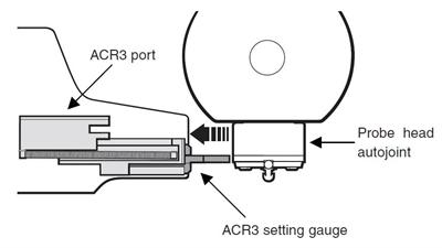
The following section describes the recommended procedure for datuming the ACR3 once it is fitted to the MRS rack and the MRS is fitted to the CMM table (please refer to 'Fitting the ACR3 to the MRS - 4 port and 8 port').
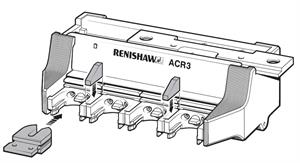
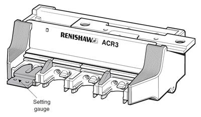
Each rack comes with a setting gauge (see below) that is designed to assist in the datuming of the ACR3.
Locating the Z position
1. Position the ACR3 so that it is in the unlocked position (positioned to the left-hand side of the travel).
2. Insert the lid clips as shown below.
NOTE: This procedure assumes the rack is aligned with the Y-axis. If the rack is aligned with the X-axis, transpose X and Y.
3. Position the ACR3 setting gauge into port 1 as shown.
4. Inhibit the probe signal. It is recommended that this is done from within the CMM software.
Use extreme caution: The machine could be crashed.
5. Remove the probe from the probe head (at the autojoint).
6. Position the autojoint puller into the central slot of the ACR3 setting piece. Take care not to move the position of the ACR3.
7. Using ~50 μm DCC incremental moves, slowly lower the autojoint face so that it just touches (machine Z-axis) onto the top face of the setting gauge. Use it as a feeler gauge to identify the correct Z-axis position for the probe head with respect to the ACR3. Record a point at this position (point A).
NOTE: More than one attempt may be required to get a 'feel' for this operation.
LIVE CMM AXES: REMAIN OUTSIDE WORKING ZONE BETWEEN Z POSITION CHECKS. DO NOT ALLOW OTHERS TO OPERATE THE CMM DURING THIS PROCESS.
8. Remove the probe head from the ACR3 setting piece.
It is not possible to use the probe to find the 'Z' position because of tolerance stackups within the probe and stylus combination.
Locating the X position
1. Move the probe head so that the external surface of the autojoint is just touching the front of the ACR3 setting piece. Use ~50 μm DCC incremental moves, to identify the correct Y-axis position.
2. Record a point at this position (point B).
3. Move the probe head clear of the ACR3 and connect the probe assembly.
NOTE: Ensure that the autojoint locking cam is positioned approximately 5° backed off from the fully locked position and enable the probe signal.
4. Remove the ACR3 setting piece from port 1.
Locating the Y position
1. Manually take four points on the top of port 1 (port1 unlocked, points 1 to 4) as shown below, to create a plane.
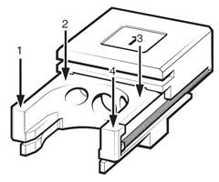
NOTE: Take care not to take a point to close to the lid clip as this may cause a problem later on in the datuming procedure.
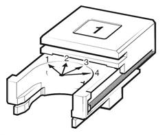
2. Manually take four points round the curved part at the rear of port 1 (port1 unlocked, circle centre). Take care to avoid the driver blade and the mounting screw holes.
3. Construct an axis system using:
- "Port1 unlocked, points 1 to 4" as the primary plane (refer to step 1)
- "Port1 unlocked, circle centre" as the secondary axis and tertiary axis origin (refer to step 2)
- Store this axis system as (axis 1)
4. The CMM can now locate ports 2 to 4 in the unlocked position under CNC control. The table below shows the nominal location of the centre of these ports, assuming that the rack is running along the CMM's Y-axis.
Port | X position | Y position |
1 | 0 | 0 |
2 | 0 | 35 |
3 | 0 | 70 |
4 | 0 | 105 |
NOTE: Dimensions in mm (in).
The recommended procedure for locating the ports is as follows (see steps 1 and 2 for reference):
- Move stylus to nominal XY centre of port
- Move stylus to 2 mm below the top surface of the port, in the current axis (axis 1) system
- Take 4 points round the curved part at the rear of the port
- Use the 4 points to create a circle, use this as a sub-datum in the XY axis
- Take 4 points on the top surface of the port
Port | X position | Y position |
1 | 8 | -13.5 |
2 | -8 | -13.5 |
3 | -8 | 13.5 |
4 | 8 | 13.5 |
NOTE: Dimensions in mm (in).
- Store the points as port* unlocked points 1 to 4
- Store the circle as port* unlocked circle 1
- Recall axis 1 (see step 3)
- Locate the next port
* Port number (e.g. 1, 2, 3 etc.).
6. If an eight port ACR3 is to be fitted to the CMM then step 7 should be completed, otherwise please go to step 8.
7. The CMM can now locate ports 5 to 8 in the unlocked position under CNC control. The table below shows the nominal location of the centre of these ports, with respect to the axis 1, assuming that the rack is running along the CMM's Y-axis.
Port | X position | Y position |
5 | 0 | 187 |
6 | 0 | 222 |
7 | 0 | 257 |
8 | 0 | 292 |
NOTE: Dimensions in mm (in).
The recommended procedure for locating 5 to 8 ports is as follows (see steps 1 and 2 for reference):
- Take a Z-axis reference point (x = 6.5 mm, y = 173.8 mm) for ACR3 in the unlocked position. Use this point as a Z-axis sub datum for locating ports 5 through 8 in the unlocked position.
- Move stylus to nominal XY centre of port
- Move stylus to 2 mm below the top surface of the port, in the current axis (axis 1) system
- Take 4 points round the curved part at the rear of the port
- Use the 4 points to create a circle, use this as a sub-datum in the XY axis
- Take 4 points on the top surface of the port
Port | X position | Y position |
1 | 8 | -13.5 |
2 | -8 | -13.5 |
3 | -8 | 13.5 |
4 | 8 | 13.5 |
NOTE: Dimensions in mm (in).
- Store the points as port* unlocked points 1 to 4
- Store the circle as port* unlocked circle 1
- Recall axis 1. (see step 3)
- Locate the next port
* Port number (e.g. 5, 6, 7 etc.).
8. Move the probe head clear of the ACR3.
9. Move the ACR3 to the locked position (positioned to the right-hand side of the travel).
10. Take a Z-axis reference point (x = 6.5 mm, y = 75.5 mm) for ACR3 position in the locked position. Use this point as a Z-axis sub datum for locating ports 1 through 4 in the locked position.
11. The CMM can now locate ports 1 to 4 in the locked position under CNC control. The table below shows the nominal location of the centre of these ports.
Port | X position | Y position |
1 | 0 | 88.96 |
2 | 0 | 123.96 |
3 | 0 | 158.96 |
4 | 0 | 193.96 |
NOTE: Dimensions in mm (in).
Recommended procedure for locating port:
- Move stylus to nominal XY centre of port
- Move stylus to 2 mm below the top surface of the port, in the current axis
- Take 4 points round the curved part at the rear of the port
- Use the 4 points to create a circle, use this as a sub-datum in the XY axis
- Take 4 points on the top surface of the port
Port | X position | Y position |
1 | 8 | -13.5 |
2 | -8 | -13.5 |
3 | -8 | 13.5 |
4 | 8 | 13.5 |
NOTE: Dimensions in mm (in).
- Store the points as portx locked points 1 to 4
- Store the circle as portx locked circle 1
- Recall axis 1 (see step 3)
- Apply Z axis reference point as a Z-axis sub-datum (see step 10)
- Locate the next port
12. If an eight port ACR3 is to be fitted to the CMM then this step should be completed, otherwise please go to step 14.
13. The CMM can now locate ports 5 to 8 in the locked position under CNC control. The table below shows the nominal location of the centre of these ports, with respect to axis 1, assuming that the rack is running along the CMM's Y-axis.
Port | X position | Y position |
5 | 0 | 275-96 |
6 | 0 | 310.96 |
7 | 0 | 345.96 |
8 | 0 | 380.96 |
NOTE: Dimensions in mm (in).
Recommended procedure for locating port:
- Take a Z axis reference point (x = 6.5 mm, y = 262.3 mm) for ACR3 in the unlocked position. Use this point as a Z-axis sub datum for locating ports 5 to 8 in the unlocked position.
- Move stylus to nominal XY centre of port
- Move stylus to 2 mm below the top surface of the port, in the current axis (axis 1) system
- Take 4 points round the curved part at the rear of the port
- Use the 4 points to create a circle, use this as a sub-datum in the XY axis
- Take 4 points on the top surface of the port
Port | X position | Y position |
1 | 8 | -13.5 |
2 | -8 | -13.5 |
3 | -8 | 13.5 |
4 | 8 | 13.5 |
NOTE: Dimensions in mm (in).
- Store the points as portx locked points 1 to 4
- Store the circle as portx locked circle 1
- Recall axis 1. (see step 3)
- Locate the next port
14. An axis system is now constructed for each of the ports. This step shows the construction steps for port 1 and should be repeated for each port:
- Construct a plane from port1 unlocked points 1 to 4 and port1 locked points 1 to 4 (port plane)
- Construct a line from port1 unlocked circle 1 and port1 locked circle 1 (port line)
- Construct an axis system (port1 axis) using:
- Port plane as the primary axis
- Port line as the secondary axis
- Port1 unlocked circle 1 as the tertiary axis and origin of the axis system
- Save axis system as port1 axis
- Repeat this for the remaining ports
15. The Z axis offset now has to be calculated as follows:
- Recall port1 axis
- Recall Point A (see 'Locating the Z position' step 7) in this axis system
- Use the following formula:
probe Z offset = Z axis of Point A * – 1
16. The probe X axis offset now has to be calculated as follows:
- Recall port1 axis
- Recall Point B (see 'Locating the X position' step 1) in this axis system
- Use the following formula:
probe X offset = X axis of Point B – 42 mm
17. Apply the Z and X probe offsets to all the ACR3 axis systems as follows, as constructed in step 14:
- Recall portx axis
- Translate the Z-axis datum position by probe Z offset
- Translate the X-axis datum position by probe X offset
- Store as portx axis
18. Move the probe clear of the ACR3.
19. Recall ACR3 axis4, move the probe head to a position of X 40 mm,Y 62.6 mm, Z 0 mm.
20. Move the ACR3 so that port 4 is located behind the position of the probe head.
21. Slowly move the probe head in the X axis to a position of X = 0 mm (probe docked into the ACR3).
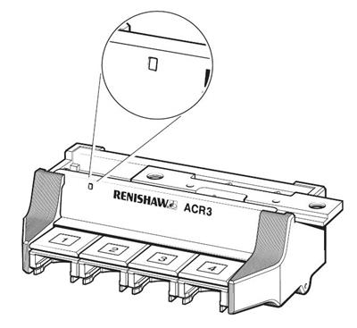
22. With the head located in port 4 move along the ACR3 Y axis using 50 µm to 100 μm DCC moves until the alignment circle is positioned in the centre of the alignment window. Record a point (point C) in this position (see below for reference).
23. The probe Y-axis offset now has to be calculated:
probe Y offset = Y axis position of point C – 62.6 mm
24. Apply the Y probe offset to all the ACR3 axis systems:
- Recall portx axis as constructed in step 17
- Translate the Y-axis datum position by probe Y offset
- Store as portx axis
25. Calculate the ACR3 traverse distance (distance):
- Recall port1 axis
- Recall port1 locked circle (refer to step 11) the Y-axis position of this feature is the traverse distance for the ACR3 (distance)
26. This traverse distance is then used in the load/unload routines.