Czym jest enkoder?
Enkodery o różnorodnej konstrukcji i zasadzie działania są wykorzystywane w wielu zastosowaniach i branżach do precyzyjnego pomiaru położenia.
Celem niniejszego artykułu jest objaśnienie zasady działania enkodera, ich różnych typów i zastosowań w różnych branżach.
Czym jest enkoder?
Enkoder to urządzenie elektromechaniczne, które zamienia informacje w jednym formacie lub kodzie na drugi format lub kod. Enkoder, taki jak ten produkowany przez firmę Renishaw, przekształca ruch liniowy lub obrotowy na sygnał elektryczny, który dostarcza informacji o położeniu, prędkości i kierunku ruchu.
Enkodery mogą wykorzystywać szereg różnych technologii pomiarowych: Firma Renishaw specjalizuje się w systemach enkoderów optycznych, indukcyjnych i laserowych. RLS, przedsiębiorstwo stowarzyszone z Renishaw, specjalizuje się w przetwornikach magnetycznych.
Co to jest enkoder optyczny i jak działa?
Enkodery optyczne to urządzenia, w których wykorzystuje się źródło światła i fotodetektor przesuwający się nad liniałem z naniesioną skalą w celu wytworzenia sygnału elektrycznego. Ten sygnał może być odczytywany przez moduł sterujący (lub sterownik) w układzie sterowania układami dynamicznymi. Firma Renishaw ma ponad trzydziestoletnie doświadczenie w projektowaniu, produkcji i pomocy technicznej w zakresie zaawansowanych enkoderów optycznych.
Enkoder optyczny składa się z dwóch podzespołów: liniału i głowicy.
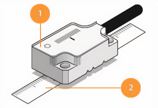
1: Głowica 2: Liniał
Liniał enkodera
Na liniałach enkoderów optycznych są naniesione równoległe, ciemne linie, podobnie jak znaczniki na standardowej linijce. Linie te, często nazywane podziałkami, są „odczytywane” przez układ optyczny wewnątrz głowicy, w wyniku czego powstają sygnały elektryczne lub obrazy do dalszej obróbki. Linie są dokładnie pozycjonowane na materiale liniału w celu zapewnienia odpowiedniej wydajności pomiarowej systemu.
Enkodery optyczne mogą mieć różne kształty, takie jak elastyczne liniowe, sztywne liniowe, dyski i pierścienie. Te różne kształty umożliwiają pomiar i sterowanie różnymi rodzajami ruchu, takimi jak ruch liniowy, pełny obrót, częściowy obrót po łuku lub kombinacja tych ruchów.
Liniały enkoderów optycznych muszą być stabilne i wytrzymałe. Są zwykle wykonane z takich materiałów, jak stal nierdzewna czy szkło.
Głowica enkodera
Głowica zawiera układ optyczny i elektroniczny, które generują elektryczny sygnał wyjściowy opisujący pozycję i kierunek ruchu głowicy odczytowej względem liniału.
Dzięki jednostce przetwarzania sygnału i cyfrowej interpolacji enkodery optyczne mają dokładność pozycjonowania do jednej miliardowej metra (1 nm).
Nanometr to promień helisy DNA, szerokość dwóch cząsteczek glukozy lub długość fali promieniowania rentgenowskiego.

Typy enkoderów optycznych
Niezabudowane enkodery
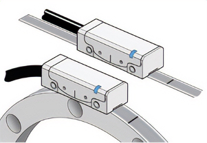
Niezabudowany enkoder optyczny ma liniał i głowicę, które są oddzielone niewielką szczeliną, znaną jako tolerancja wysokości przesuwu. Jego konfiguracja umożliwia pomiar liniowy, obrotowy lub na łuku częściowym. Bezdotykowa konstrukcja oznacza zerowe tarcie, brak zużycia mechanicznego czy też histerezy.
Zabudowane enkodery
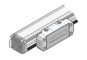
W systemach zabudowanego enkodera liniał i głowica są zamontowane w szczelnej obudowie, która chroni go przed zanieczyszczeniami stałymi i wnikaniem płynów w trudnych warunkach środowiska roboczego. Przykładowo, zabudowane enkodery są zwykle stosowane w obrabiarkach, gdzie ważna jest wysoka dokładność i odporność na zanieczyszczenia pozostałościami po obróbce i chłodziwem.
Ruch
Enkodery optyczne mogą mierzyć różne formy ruchu, w zależności od rodzaju i struktury obrabiarki.

Liniowy
Enkodery liniowe nadają sygnał położenia wzdłuż linii prostej. Są używane w osiach X, Y lub Z, np. w kartezjańskiej maszynie współrzędnościowej (CMM).

Obrotowy
Enkodery obrotowe informują o pozycji kątowej obracającej się części przy pomocy liniału w kształcie pierścienia lub dysku. Te enkodery umożliwiają sterowanie ruchem obrotowym, np. w stole obrotowym lub przegubach robota.

Łuk częściowy
Niektóre liniały enkoderów liniowych są elastyczne i można je owinąć wokół bębna, wału lub zakrzywionej powierzchni maszyny, aby umożliwić sterowanie ruchem obrotowym mniejszym niż jeden pełny obrót.
Jakie są różnice między enkoderami absolutnymi oraz inkrementalnymi?
Enkodery inkrementalne mogą wykrywać ruch tylko względem ich bieżącej pozycji lub znanego elementu odniesienia. Wyjściowy sygnał położenia zwiększa lub zmniejsza (w zależności od kierunku) pozycję o jedno zliczenie na raz, gdy głowica enkodera porusza się względem liniału.
Enkodery absolutne natychmiast dekodują aktualne położenie bez konieczności wykonywania jakiegokolwiek ruchu.
Kluczową różnicą między działaniem enkodera inkrementalnego i absolutnego jest reakcja na utratę zasilania. Jeśli enkoder absolutny utraci zasilanie, głowica nadal będzie w stanie poprawnie zgłosić bieżące położenie po przywróceniu zasilania, nawet jeśli poruszyła się podczas przerwy w zasilaniu. Enkodery inkrementalne tracą informacje o położeniu podczas przerwy w zasilaniu i wymagają ponownego uzyskania położenia odniesienia po przywróceniu zasilania.
Kolejna, kluczowa różnica jest związana z komunikacją: enkodery absolutne mają dwukierunkową komunikację szeregową między sterownikiem a głowicą, podczas gdy enkodery inkrementalne zapewniają jednokierunkową komunikację za pośrednictwem sygnałów analogowych lub cyfrowych z głowicy do sterownika.
Położenie inkrementalne
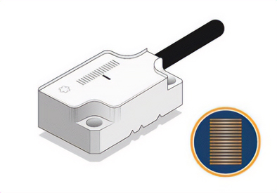
Linie na skali inkrementalnej są ułożone w prosty, równoległy wzór, jak linijka bez cyfr. Podczas procedury rozruchowej położenie odniesienia jest wykrywane przez odczyt znacznika odniesienia osadzonego w obrębie skali inkrementalnej. Punkt bazowy to pojedynczy, stały punkt w dowolnym miejscu wzdłuż osi pomiarowej, którego używa się jako punktu odniesienia obrabiarki. Jest czasami określany jako położenie wyjściowe. Wszystkie informacje o położeniu odnoszą się do tego punktu odniesienia.
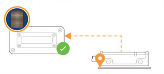
Enkoder inkrementalny wysyła informacje o swoim położeniu w postaci dwóch, analogowych sygnałów wyjściowych przesuniętych względem siebie w fazie o 90 stopni (jak przebieg sinusoidalny i kosinusoidalny) lub jako dwa sygnały cyfrowe oddalone od siebie o 90 stopni (znane jako sygnały kwadraturowe). Sygnały te mogą być interpretowane przez sterownik w celu obliczenia wielkości i kierunku ruchu wzdłuż liniału enkodera.
Skala inkrementalna enkodera może być produkowana w długich odcinkach dla instalacji wielkoskalowych lub przycinana w celu dopasowania do dowolnej długości osi.
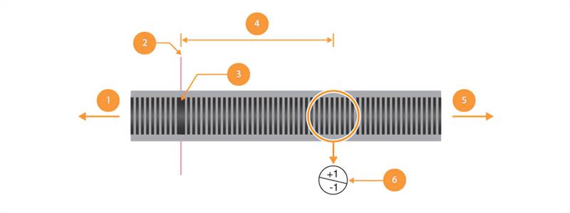
1: Kierunek malejącego zliczania, 2: Położenie punktu odniesienia, 3: Znacznik odniesienia, 4: Położenie sterownika = liczba zliczeń od punktu odniesienia, 5: Kierunek narastającego zliczania, 6: Zmiana liczby inkrementalnej
Położenie absolutne
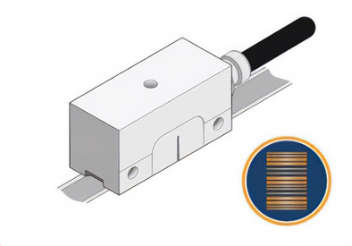
W systemie enkodera absolutnego informacje o położeniu absolutnym są zakodowane we wszystkich sekcjach liniału, podobnie jak linijka z cyframi. Te swoiste pozycje są definiowane przez zestawy równoległych linii, w których brakuje niektórych z nich, co przypomina raczej kod kreskowy. Ten niepowtarzający się wzorzec umożliwia głowicy wykrycie swojego położenia natychmiast po uruchomieniu.
Sterownik będzie okresowo żądał informacji o położeniu od głowicy, która następnie przechwytuje obraz migawkowy liniału i dekoduje go w określonym położeniu, które jest następnie zgłaszane z powrotem do sterownika za pośrednictwem protokołu komunikacji szeregowej.
Dostępnych jest wiele standardowych w branży metrologicznej protokołów komunikacyjnych, często powiązanych z konkretnymi producentami sterowników obrabiarki.
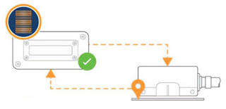
Liniały absolutne bazują na krótkich, unikalnych wzorach (lub słowach) linii i spacji w celu identyfikacji położenia absolutnego. Ponieważ słowa te mają skończoną liczbę możliwych układów, liniały enkoderów absolutnych będą miały maksymalną długość pomiarową. W przypadku systemu enkodera absolutnego RESOLUTE™ firmy Renishaw ta maksymalna długość pomiarowa wynosi 21 metrów.
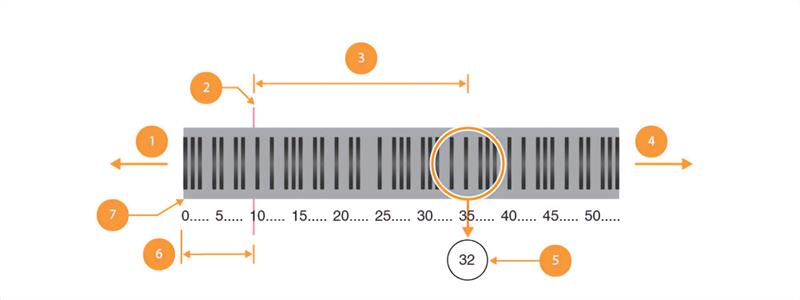
1: Kierunek malejącego położenia, 2: Położenie punktu odniesienia, 3: Położenie sterownika = położenie głowicy – przesunięcie liczbowe, 4: Kierunek narastającego położenia, 5: Położenie absolutne, 6: Przesunięcie liczbowe punktu odniesienia, 7: Położenie „zerowe”
Gdzie warto zastosować enkoder inkrementalny?
Enkodery inkrementalne są wykorzystywane w wielu różnych zastosowaniach sterowania przemieszczeniami, takich jak automatyzacja fabryk, maszyny współrzędnościowe (CMM) i urządzenia do produkcji półprzewodników. Enkodery inkrementalne umożliwiają dokładny pomiar położenia przy drobnych rozdzielczościach i dużych prędkościach skanowania.
Gdzie warto zastosować enkoder absolutny?
Enkodery absolutne dobrze nadają się do maszyn, które muszą zachowywać informacje o położeniu po wyłączeniu i włączeniu zasilania. Zastosowania te obejmują roboty chirurgiczne i maszyny, w których cykle naprowadzania na stały znacznik odniesienia nie są pożądane.
Gdzie są stosowane enkodery optyczne?
Enkodery optyczne to uniwersalne urządzenia do pomiaru położenia, wykorzystywane w szerokim zakresie zastosowań do pomiaru i sterowania ruchem liniowym lub obrotowym.
Znajdują one zastosowanie w wielu branżach i zastosowaniach, takich jak metrologia, produkcja półprzewodników, robotyka, automatyka, obrabiarki i badania naukowe.
Czym jest enkoder indukcyjny?
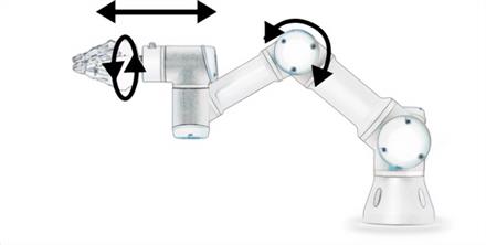
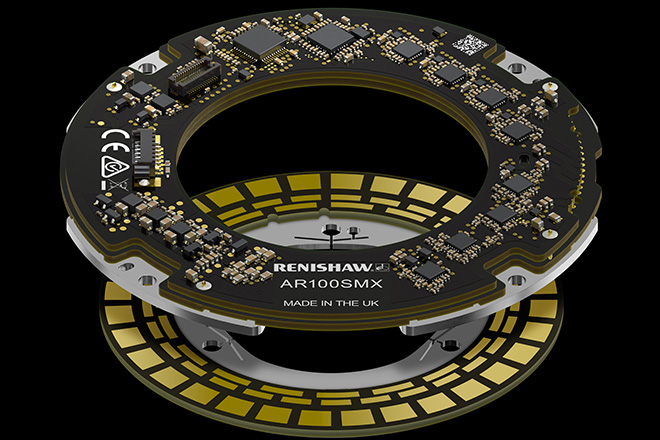
Indukcyjny enkoder absolutny to taki czujnik położenia, w którym wykorzystano zjawisko indukcji elektromagnetycznej do pomiaru położenia lub ruchu osi.
Enkodery indukcyjne charakteryzują się solidną budową, odpornością na zanieczyszczenia, wysoką dokładnością i odpornością na działanie zewnętrznych pól magnetycznych.
Znajdują zastosowanie w mocowaniach przegubowych, urządzeniach medycznych, ogólnych układach automatyki, bezzałogowych statkach latających (UAV), robotach i silnikach serwomechanizmów.
Aby dowiedzieć się więcej, odwiedź stronę internetową poświęconą enkoderom indukcyjnym firmy Renishaw.
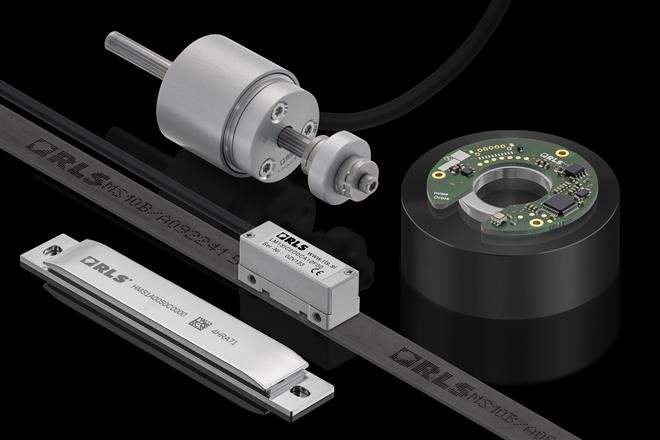
Czym jest enkoder magnetyczny?
W systemach enkoderów magnetycznych wykorzystuje się namagnesowany liniał z szeregiem naprzemiennych biegunów magnetycznych. Głowica porusza się wzdłuż liniału; zawiera ona czujnik wykrywający zmianę natężenia pola magnetycznego podczas ruchu i przekształcający tę zmianę w sygnał elektryczny.
Enkodery magnetyczne są często wykorzystywane w robotyce (zautomatyzowane pojazdy kierowane) i zastosowaniach drukarskich.
Aby dowiedzieć się więcej o systemach enkoderów magnetycznych, odwiedź witrynę internetową RLS.
Czym jest enkoder laserowy?
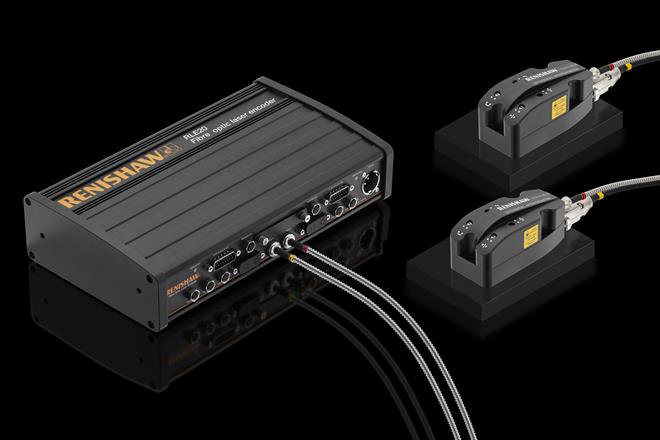
Enkoder laserowy wykorzystuje długość fali światła laserowego jako jednostkę pomiarową, wykrywając różnicę długości między stałą ścieżką odniesienia a zmienną ścieżką pomiarową. Enkodery laserowe charakteryzują się wysoką dokładnością pozycjonowania i precyzyjną rozdzielczością.
Są często wykorzystywane w przemyśle lotniczym i morskim, a także w innych specjalistycznych zastosowaniach.
Aby dowiedzieć się więcej, odwiedź witrynę poświęconą enkoderom laserowym firmy Renishaw.
Obejrzyj nasze webinarium na żądanie
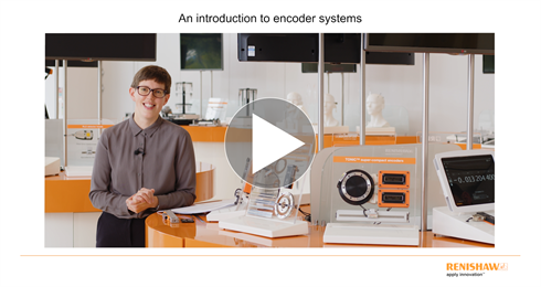
Webinarium wprowadzające do systemów enkoderów przedstawia w prosty sposób, czym jest enkoder.
Objaśnia przeznaczenie liniału i głowicy, zasadę działania enkodera, ich różne typy i zastosowania w różnych branżach.
Zarejestruj się, aby obejrzeć materiał na żądanie.
Skontaktuj się z naszym zespołem ds. sprzedaż
Skontaktuj się z lokalnym biurem, aby uzyskać więcej informacji i porozmawiać z ekspertem.
