Navigation
DMIS program sequence
Load the DMIS part program into your metrology software.
The DMIS program is written as a series of manual steps to establish a coordinate system on the MCG pilar, then switches to automatic to capture and record the required data points.
The part program first asks the operator to agree as liability statement.
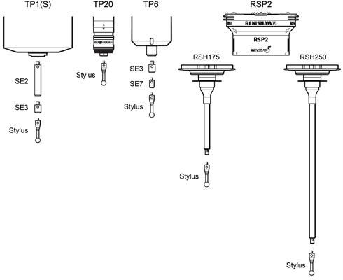
NOTE: The MCG is not suitable for use with TP7M, SP600 or SP80 probes, and not recommended for use with TP200 probes. SP25M requires a TM25-20 and TP20 module. Attach the special, calibrated stylus of the MCG (this can be readily identified by the two grooves cut within the stylus stem) to your touch-trigger probe. If necessary, use the extensions and adaptors supplied to allow the calibrated stylus to be fitted to the probe.
The program advances and pauses to prompt the operator to capture five data points around the MCG pivot.
NOTE: This centre is not important for the metrology analysis but is only used to generate the target points on the MCG.
The origin of the part program is moved to the centre of the MCG pivot. The machine is set to auto mode and the tip will move along the X-axis of the machine in the positive direction so the MCG arm can be fitted. At the end of the move the operator is asked to engage the MCG arm on the pivot and on the probe.
The program collects the points on the MCG arm, starting form the points on the equator, then the points on the north latitude and finally the points on the south latitude. At the end of the program the co-ordinates of the points are exported.