Navigation
Aligning the rack
Rack base
For smooth wear-free running of the autochange system, correct alignment of the ACR1 to the CMM axes is essential.
The adjustable rack base enables the rack to be aligned quickly and precisely with the axes of the CMM.
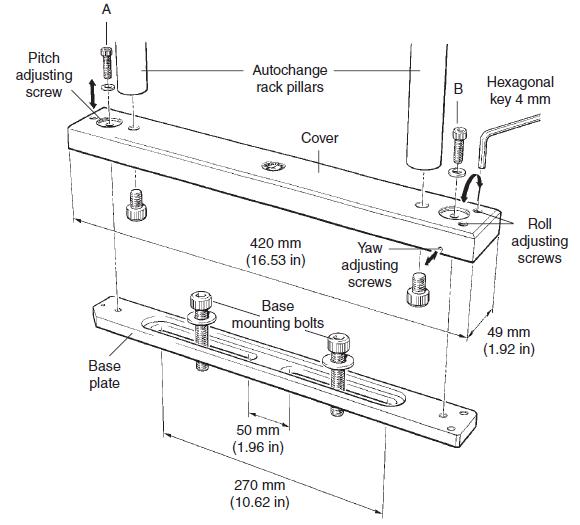
Three independent adjusters are used to align the rack in roll, pitch and yaw.
The rack base is designed not to cause damage to the CMM table.
For full rack base assembly and mounting instructions, see the autochange system installation and programmer's guide (Renishaw part number H-1000-6012).
If it is necessary to remove the rack from the CMM table, loosen one yaw adjusting screw and remove screws A and B. The rack may now be lifted off its mounting.
Replacement is the reverse of removal, with very little, if any, re-aligning required, due to the ‘repeatability' of the rack base structure.
Refitting and adjusting the rack base
1 Unscrew the roll and pitch adjusting screws so that they are near the end of their travel.
2 Mount the cover on to the rack base. It is recommended that the ACR1 is supported before screws A and B are fitted.
3 Hand tighten screws A and B until resistance is felt.
4 Use the hexagonal key to tighten down the roll and pitch adjusting screws until resistance is felt. Tighten the screws another 3/4 of a turn. The rack base is now set at the mid position of the adjusting range. Fine adjustment can now be carried out as required.
5 When adjustment is complete, tighten down screws A and B firmly. Maximum torque is 8 N/m (5.9 lbf/ft).
Rack base specification
Yaw adjustment range about the nominal centre position | 1 mm (0.04 in) |
|---|---|
Pitch adjustment range nominal limit | 1 mm (0.04 in) |
Roll adjustment range nominal limit | 1 mm (0.04 in) |
Overall base height when assembled | 26 mm (1.02 in) |
Base mounting bolts up to 10 mm (0.39 in) can be used.
Rack adjustment limits
When the rack has been mounted onto the rack base (see the autochange system installation and programmer's guide, Renishaw part number H-1000-6012), the following checks should be made - adjusting the base pitch, roll and yaw as and when necessary.
Docking station run-out:
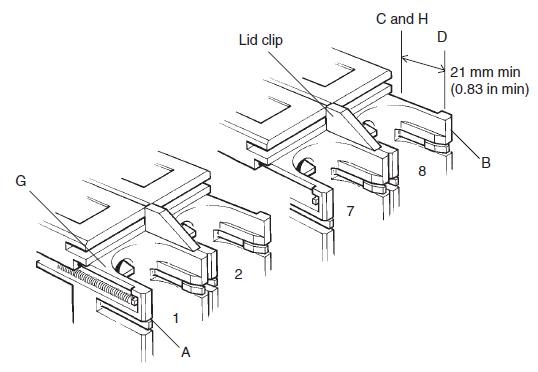
1 Ensure the run-out along the top of one of the docking ports (between C and D) is less than 50 µm (0.002 in).
2 Ensure the run-out along the front face, (between points A and B) is less than 100 µm (0.00 4in).
3 Ensure the run-out across the eight docking ports between points G and H is within 100 µm (0.00 4in).
The adjustment limits given are maximum values - the better the alignment, the longer the life and trouble-free operation of the system.
NOTE: These instructions apply to both horizontal and vertical rack mounting.