Navigation
Installation procedure
WARNING: Ensure the PI 200-3 is disconnected from the power adapter during installation.
WARNING: Take care not to exceed the operation ambient of 50 °C around the unit. Do not install near sources of heat. Forced cooling may be required in final installation.
Inserting PI 200-3 card into PHC10-3 PLUS
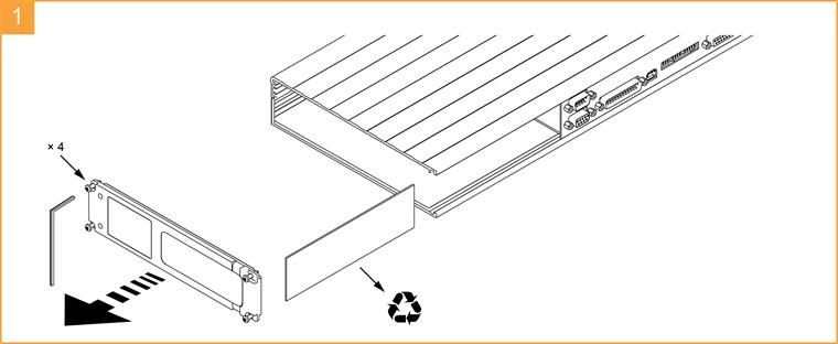
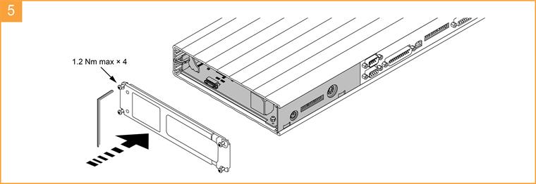
Remove the end panel of the PHC10-3 PLUS with a hex-key and slide out the blanking plate.
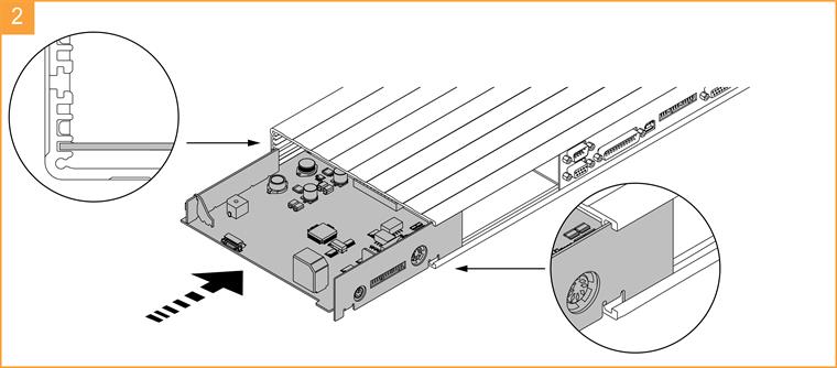
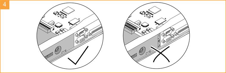
Insert the PI 200-3 card, ensuring that the card is located in the correct grooves shown in the illustration below.
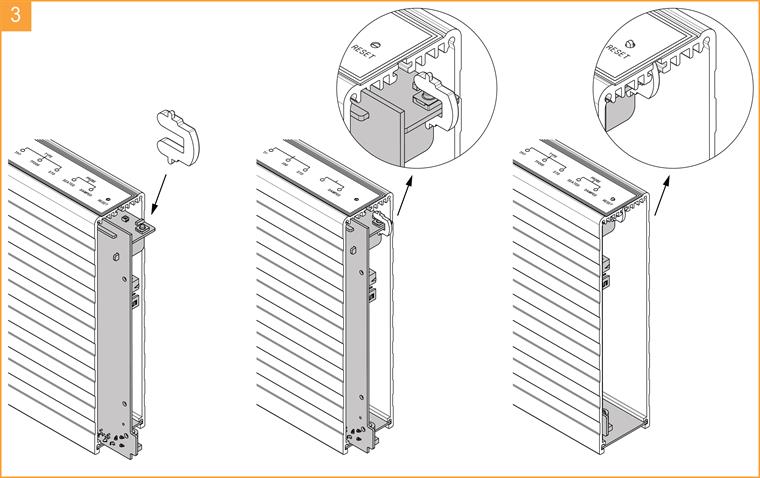
Insert the reset actuator over the top of the reset button on the PI 200-3 card and then replace the end panel.
Upgrading to TP200 (retrofit)
To successfully retrofit a TP200 probe system, the following points will need to be considered:
- The CMM controller must service the PICS - PDAMP control signal - upgrade of the controller may be necessary if this signal is not available
- The probe signal wires from the M8 connector on the probe head must be routed directly to the PI 200 interface - if an in-line interface for kinematic switching probes (TP1 / TP2 / TP6) is present, it must be removed
- The signal wire resistance must be less than 5 ohms per conductor
- Some experimentation with typical stylus arrangements may be necessary to obtain a satisfactory setting for the PDAMP / HALT filter delay time - the trigger / reseat debounce time and other configuration options will also need to be set (refer to the‘configuration switches' section for more information)
- If upgrading from TP2, measurement programs may need to be changed to suit the length of the TP200, which is 5 mm longer than the TP2
- If upgrading from TP2, star or offset (cranked) stylus arrangements will require a minimum 5 mm extension piece to be added for use with the TP200
- If cables other than those supplied by Renishaw are used, equivalent cable screening and connector bonding must be used to maintain compliance with the EMC standards
System interconnection
Interconnection diagrams for the most common product combinations. Consult the appropriate product installation guide for information about setting the configuration switches of the PHC10-3 PLUS or ACC2-2 system controllers:
- PH10 PLUS series installation and user's guide (Renishaw part number H-1000-7592)
- Autochange system installation guide (Renishaw part number H-1000-6010)
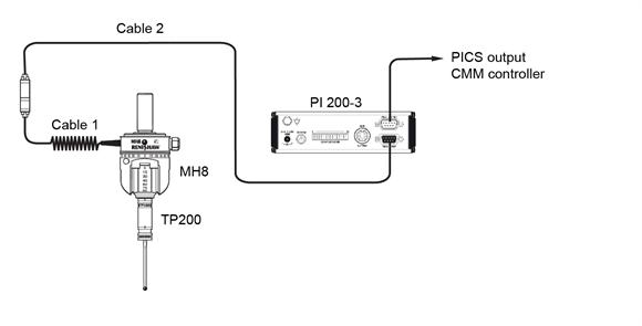
PI 200-3 interconnection with MH8
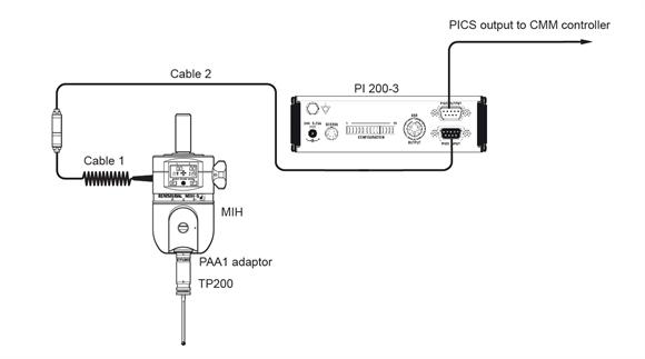
PI 200-3 interconnection with MIH head
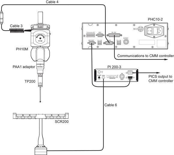
PHC10-2 and PI 200-3 interconnection with PH10M
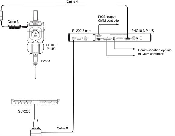
PI 200-3 card with PHC10-3 PLUS interconnection with PH10T PLUS and SCR200
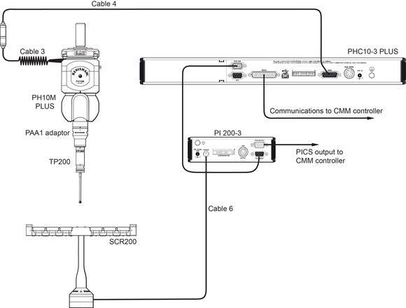
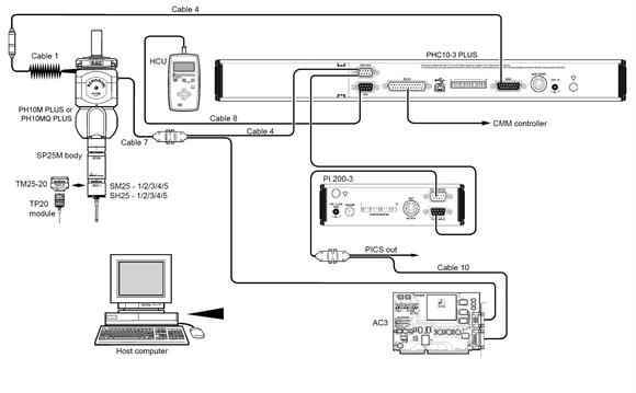
PI 200-3 with PHC10-3 PLUS interconnection with PH10M PLUS and SCR200
PI 200-3 card and PHC10-3 PLUS interconnection with PH10 PLUS and AC3
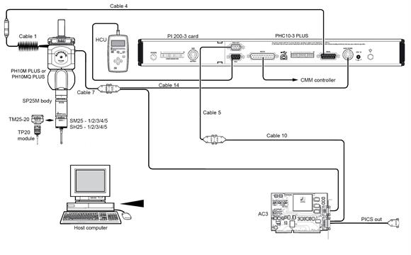
PI 200-3 and PHC10-3 PLUS interconnection with PH10 PLUS and AC3
Using TP200 with the ACR1 autochange system
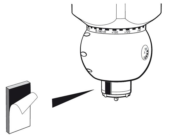
The CMM controller must assert the probe damping signal (PDAMP) on the PICS port when the probe is approaching the rack, to prevent a false trigger being generated when the probe contacts the docking port lid. If this is not possible, a shock absorbing pad (part number A-1085-0294 supplied with ACR1) must be fitted to the autojoint connector on the probe head at the point of contact with the port lid.
SCR200 stylus change rack
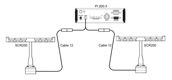
PI 200-3 and two SCR200 racks
The miniature DIN connector on the base of the SCR200 rack is connected to the SCR200 connector on the PI 200-3 rear panel using cable PL63 / PL64 / PL65 according to the length required. For applications requiring two racks, a dual rack splitter cable is needed. SCR200 adaptor cable must be fitted at the PI 200-3 end.
Interconnection cables
Cable number | Cable ident | Length | Part number | Notes |
|---|---|---|---|---|
1 | PL1 | 260 mm to 710 mm (10.24 in to 27.95 in) | A-1016-0004 | Coiled |
1 | PL2 | 410 mm to 1.27 m (16.14 in to 50 in) | A-1016-0006 | Coiled |
1 | PL3 | 680 mm to 2.32 m (26.77 in to 91.34 in) | A-1016-0012 | Coiled |
1 | PL4 | 4.5 m (177.17 in) | A-1016-0001 | Plain |
1 | PL27 | 225 mm to 450 mm (8.86 in to 17.72 in) | A-1016-6370 | Coiled |
1 | PL29 | 740 mm to 1.48 m (29.13 in to 58.27 in) | A-1016-6420 | Coiled |
2 | PL22 | 0.4 | A-1057-0131 | |
3 | PL5 | 400 mm to 800 mm (15.75 in to 31.5 in) | A-1016-0131 | Coiled |
3 | PL6 | 800 mm to 1.6 m (61.5 in to 62.99 in) | A-1016-7673 | Coiled |
3 | PL12 | 100 mm (3.94 in) | A-1016-7674 | Plain |
3 | PL13 | 100 mm to 200 mm (3.94 in to 7.87 in) | A-1016-7675 | Coiled |
4 | PLM6 | 6 m (236.22 in) | A-1016-7564 | Unterminated on end |
4 | PLM7 | 4 m (157.48 in) | A-1016-7563 | Unterminated on end |
4 | PLM8 | 6 m (236.22 in) | A-1016-7677 | |
4 | PLM9 | 4 m (157.48 in) | A-1016-7678 | |
5 | PL25 | 300 mm (11.81 in) | A-1016-0124 | |
6 | PL63 | 5 m (196.85 in) | A-1016-7630 | |
6 | PL64 | 10 m (393.7 in) | A-1016-7631 | |
6 | PL65 | 20 | A-1016-7632 | |
7 | PL38 | 25 m (984.25 in) | A-1016-7625 | Unterminated on end |
7 | PL42 | 15 m (590.55 in) | A-1016-7624 | Unterminated on end |
7 | PL56 | 12 m (472.44 in) | A-1016-7626 | Unterminated on end |
7 | PL44 | 8 m (314.96 in) | A-1016-7627 | Unterminated on end |
7 | PL46 | 3.7 m (145.67 in) | A-1016-7628 | Unterminated on end |
7 | PL45 | 1.8 | A-1016-7629 | Unterminated on end |
8 | PL70 | 2 | A-1016-7634 | |
9 | PL76 | 1 | A-1016-7643 | |
10 | PL112 | 1 | A-2172-0004 | |
11 | PL97 | 0.25 | A-1016-7660 | |
12 | PL63 | 5 m (196.85 in) | A-1016-7630 | |
12 | PL64 | 10 m (393.7 in) | A-1016-7631 | |
13 | PL65 | 20 | A-1016-7632 | |
14 | PL172 | 0.75 | A-5684-1000 |
Rack mounting
Mounting PI 200-3
To mount the PI 200-3 in a 19 inch cabinet, two 1/3 blanking panel kits are required (Renishaw part number A-1018-0179). Fit the panels using the M5 × 6 mm long screws provided.
Mounting PI 200-3 with PHC10-2
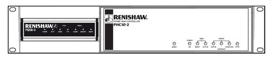
To mount a PI 200-3 next to a PHC10-2 controller in a 19 inch cabinet, a bracket kit is required (Renishaw part number A-1018-0173). Fit the panels using the M5 × 6 mm long screws provided.