Navigation
PH20 head touch metrology data
Procedure
The axis and centre of a 25 mm diameter ring gauge was determined and the ring was divided into 24 equal segments. For each of the 24 segments, a set of points was taken at various speeds and a best-fit circle fitted using all 24 sets of points. Each point was then projected to the best fit circle and the radial variation of each set of points was plotted.
For PH10 and PH20 CMM touch points:
At each of the 24 segments, 50 points were taken at each speed before moving onto the next segment. The touch speed started at 10 mm/s, increasing by 5 mm/s up to a maximum of 25 mm/s.* This gave a set of 200 points per segment, 4800 points in total.
* The maximum CMM acceleration limited the max. CMM speed to 25 mm/s
For PH20 head touch points
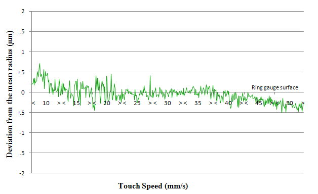
The method was identical to that above but a total of 450 points were taken at each segment starting at 10 mm/s and increasing in 5 mm/s increments up to 50 mm/s.
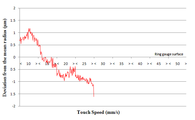
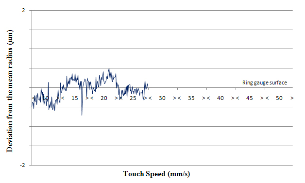
The graphs below show that PH20 can increase and vary probing speed without affecting repeatability of position.
Requirements
PH10 graph:
PH20 CMM touch graph:
PH20 head touch graph:
Common criteria for test results given above | ||
Test site | Renishaw UK | |
Styli used | Renishaw's M2 stylus range | |
CMM specification | U3 = 2.0 + L / 350mm | |
CMM controller | UCC2 | |
Artefacts used | Æ25 mm ring gauge | |