Navigation
Probe signals
Renishaw strongly recommends that SP25M be integrated using either the AC3 card or UCC controller. However, for those OEMs who wish to integrate without them, the following information is provided to assist in dealing with the probe outputs.
Grounding arrangement
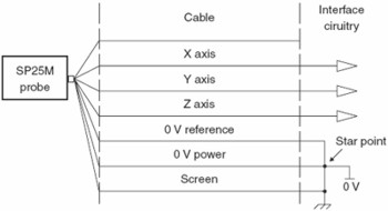
The SP25M has two 0 V connections, 0 V power and 0 V reference. It is recommended that they are connected to a star point in the interface and kept separate from the probe screen as shown below.
- The 0 V power is used to power the internal circuitry and transducers
- The 0 V reference is a signal from which the outputs are referenced
Screening
It is recommended that the screening arrangements are based on the Faraday cage principle with the screen being continuous throughout the system. The SP25M connector shell is connected to the body of the probe.
Power supply filtering
The power supply to the probe should be filtered as close to the interface output connector as possible to reduce the output noise to <20 mV RMS in the frequency range 0 kHz to 7 kHz.
Measurement signal filtering
The input bandwidth is 700 Hz. The measurement signals should be filtered as close to the interface connector as possible to stop high frequency noise getting into the interface. It is recommended that a first order filter with a 3 dB cut-off frequency of ~700 Hz is used.
Probe cable terminations
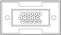
The probe cable terminates at the high-density, D-type plug and carries the signals shown in the table below:
HDD pin numbers | Wire colour | Signal description |
|---|---|---|
11 | Orange | p |
4 | Violet | q |
5 | Yellow | r |
6 | Red | +12 V |
7 | Blue | -12 V |
12 | Blue / white | 0 V reference |
1 | Brown | +5 V |
3 | Green | 0 V - power |
10 | Coax inner | Over-range |
8 | White | Probe identification |
14 | Black / white | Head LED anode |
15 | Brown / white | Head LED cathode |
13 | Black | 2 wire probe signal |
Shell | - | Screen |
Total number of connections = 14