Navigation
Automatic operation
This section gives a suggested method for datuming an ACR2 autochange rack port and the recommended CMM movements for change cycles using that datum position.
Port datum procedure
This method allows datuming of each ACR2 port by taking probing points on one of the location pins.
1. Qualify the PHS1 and probe combination (see following figure).
NOTE: The probe tip must be qualified before the port can be datumed. Refer to the PHS1 calibration guide (Renishaw part number H-1000-4048) for recommended probe calibration procedure.
A typical probe assembly suitable for port datuming would be:
- HA-8 probe arm
- TP20 probe
- PS17R 20 mm stylus
Nominal offset values for this probe assembly are:
- RD 72 mm
- RE 104 mm
The values RD and RE should be established to within ±0.1 mm by the probe qualification procedure.
NOTE: The angular orientation of the D and E axes required for port datuming (D 0°, E 0°). The probe tip should be aligned to the axis origins to within 0.1°.
Probe calibration:
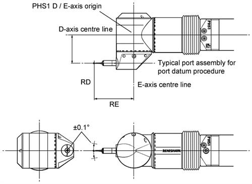
NOTE: Angular orientation of D and E axes required for port datum procedure (D and E 0°).
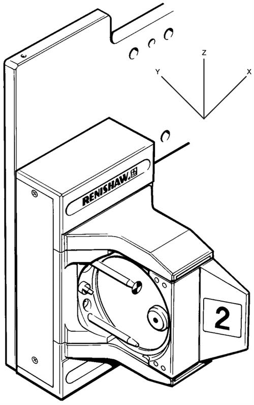
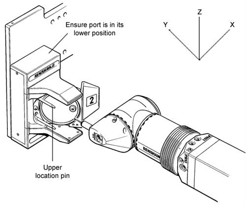
2. Position the ACR2 port in the lower latched position (see figure below).
Port in lower latched position:
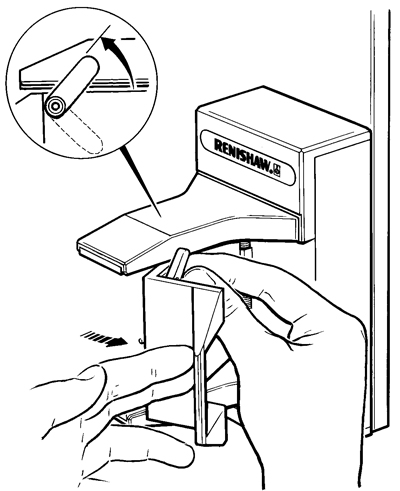
NOTE: To move between upper and lower positions manually, the two port pins must be pushed to the left to disengage the motion locks.
3. Lift the lid retaining clip to hold the latch in an open position (see figure below).
Lift the lid retaining clip:
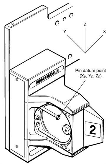
4. Take four points around the full diameter of the upper location pin in the ZX plane (assuming the rack is oriented to the CMM axes as shown).
ACR port datuming procedure:
NOTE: Only one port is shown for clarity.
5. Use the four points to create a circle.
6. Use the centre point of the circle as the coordinates for the pin datum in the X and Z axes, XP and ZP.
7. Take one point on the end of the upper location pin in the Y axis and use it as the coordinate for the pin datum in the Y axis, YP.
Pin datum position:
8. Offset the position XP, YP, ZP to the PHS1 D/E axis origin as shown below. Use this point XD, YD, ZD as the pin datum point.
XD = XP - RD
YD = YP + RE
ZD = ZP