Navigation
Machine I/O (44W HDD socket)
The machine I/O socket is used to provide connections for the CMM input / output. The cable needs to be created by the CMM installer using the pin out guide below. The connector for the machine I/O socket is provided within the UCC AI kit.

| Pin | Function | Pin | Function |
|---|---|---|---|
| 1 | External I/O +24 V | 23 | Crash |
| 2 | /Enable air solenoid/ (active low) | 24 | Reserved |
| 3 | /Axis 0 brake/ (active low) | 25 | Axis 0 positive outer limit |
| 4 | /Axis 1 brake/ (active low) | 26 | Axis 0 negative outer limit |
| 5 | /Axis 2 brake/ (active low) | 27 | Axis 1 positive outer limit |
| 6 | Uncommitted output 0 | 28 | Axis 1 negative outer limit |
| 7 | Uncommitted output 1 | 29 | Axis 2 positive outer limit |
| 8 | Uncommitted output 2 | 30 | Axis 2 negative outer limit |
| 9 | Uncommitted output 3 | 31 | Axis 0 positive inner limit |
| 10 | Uncommitted output 4 | 32 | Axis 0 negative inner limit |
| 11 | Uncommitted output 5 | 33 | Axis 1 positive inner limit |
| 12 | Uncommitted output 6 | 34 | Axis 1 negative inner limit |
| 13 | Uncommitted input 0 | 35 | Axis 2 positive inner limit |
| 14 | Uncommitted input 1 | 36 | Axis 2 negative inner limit |
| 15 | Uncommitted input 2 | 37 | 0 V |
| 16 | Uncommitted input 3 | 38 | /Axis 3 brake/ (active low) |
| 17 | Uncommitted input 4 | 39 | Axis 3 positive outer limit |
| 18 | Uncommitted input 5 | 40 | Axis 3 negative outer limit |
| 19 | Reserved | 41 | Axis 3 positive inner limit |
| 20 | De-clutch | 42 | Axis 3 negative inner limit |
| 21 | Reserved | 43 | Reserved |
| 22 | Low air pressure | 44 | 0 V |
| Shell | Screen |
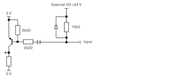
All input pins
The inputs are activated by being pulled down to 0 V. They are not opto isolated and are pulled up to +24 V by a 10 kΩ resistor within the UCC AI. These inputs can accept signal levels in the range of +5 V to +24 V, and need to be pulled below 1.5 V to signify the active state. The input pin must be driven above 4.2 V, or left open circuit, to signify the inactive state.
WARNING: The input pins must not be driven above 24 V.
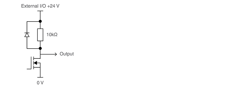
All output pins
The open drain output with a 10 kΩ pull-up resistor to external I/O +24 V is suitable for driving devices in the range +5 V to +24 V and can sink a maximum current of 200 mA. If this output is not required, then it should be left as an open circuit.
WARNING: The output pins must not be driven above 24 V.
External I/O +24 V
External I/O +24 Vdc supply is provided for use with the I/O equipment. Maximum current 1 A (1000 mA).
NOTE: Please be aware that the 1 A current is shared between the machine I/O and servo power amplifier connectors.
NOTE: All I/O peripherals should be supplied from the +24 V I/O pin.
Enable air solenoid
An active low signal to engage an air solenoid.
Brake
These outputs (pins 3, 4, 5 and 38) are used to disengage the CMM axis brakes if fitted. These outputs become active as soon as the CMM servos are engaged. During the commissioning process it is possible to invert the output from the brake connections from an active low signal to an active high signal.
Uncommitted inputs
These input pins can be configured to the customer's requirements via the UCCsuite software.
Uncommitted outputs
These output pins can be configured to the customer's requirements via the UCCsuite software.
De-clutch
This input on pin 20 should be pulled down to the 0 V line, to signal to the controller that the CMM's drives are mechanically connected to the moving elements of the machine (i.e. in their normal condition). The input should be open circuit, or held high, when the CMM has been temporarily 'de-clutched' from the drive motors to allow manual positioning. The servo system will not drive the motors in this condition and will resume control at the machine's current position when the signal goes low. The de-clutch signal can be inverted using the UCCsuite software.
Low air pressure
The low air pressure signal should be connected to a suitable air pressure switch. This input is monitored by the controller and when activated will remove power from the motors by causing a system fatal fault. During the commissioning process it is possible to invert this signal from an active low signal to an active high signal. If this capability is not required for integration to the system then the signal should be connected to the 0 V or inverted during commissioning.
Crash
The crash signal is used to inform the UCC AI of a collision of the mechanical structure of the machine. Typically this is a sensor that is fitted to the end of the CMM quill and if activated will remove power from the motors by causing a system fatal fault.
During the commissioning process it is possible to invert this signal from an active low signal to an active high signal. If this capability is not required for integration to the system then the signal should be connected to the 0 V or inverted during commissioning.
Limit switches
The UCC AI controller supports both inner and outer limit switches for each of the machine axes. During the commissioning process it is possible to invert these signals from an active low signal to an active high. If this capability is not required for integration to the system then they should be connected to the 0 V or inverted during commissioning.
Inner limit switches
If an inner limit is activated the UCC system will perform a maximum movement de-acceleration in all axes to a stop and then perform a controlled axis back-off in the opposite direction, as if a trigger event occurred.
Outer limit switches
If an outer limit is activated the UCC system will immediately disengage all servo power to the machine drives. Recovery of this error is only possible by removing the outer limit switch activation (i.e. by moving the machine off of the switch).
0 V
This is the 0 V reference for all of the I/O signals.