Navigation
UCC S5 system connection
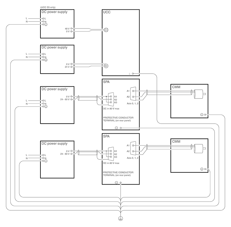
Earth bonding scheme
Installation for up to 3 axes with head cable less than 25 m

Key | Description | Key | Description |
1 | Orange head cable | 6 | 24 V power supply (supplied) |
2 | CAT 5E 300 mm cable (supplied) | 7 | 25 V - 80 V power supply (not supplied) |
3 | 16 / 0.2 mm earth connection | 8 | Air filter (supplied) |
4 | MCU connection | 9 | 48 V power supply (supplied) |
5 | CAT 5E Ethernet cable (5 m cross-over cable supplied) to host PC |
Installation for 4 - 6 axes with head cable exceeding 25 m and thermal effect compensation (TEC)

Key | Description | Key | Description |
1 | Orange head cable | 8 | 25 V - 80 V power supply (not supplied) |
2 | CAT 5E 300 mm cable (supplied) - primary | 9 | Air filter |
3 | CAT 5E 300 mm cable (supplied) - secondary | 10 | 48 V power supply (supplied) |
4 | 16 / 0.2 mm earth connection | 11 | E-STOP link cable (supplied) |
5 | MCU connection | 12 | Head comms signal booster |
6 | CAT 5E Ethernet cable (5 m cross-over cable supplied) to host PC | 13 | TEC input |
7 | 24 V power supply (supplied) |
The REVO-2 head and CMM system are operated through UCCserver which uses I++DME command protocol to communicate between the system application software and the UCC S5.
Full 5-axis scanning capability is achieved through interaction between the UCC S5, the REVO-2 and the SPA3-2, to co-ordinate all the motion and metrology aspects across the three CMM axes and the two head axes.
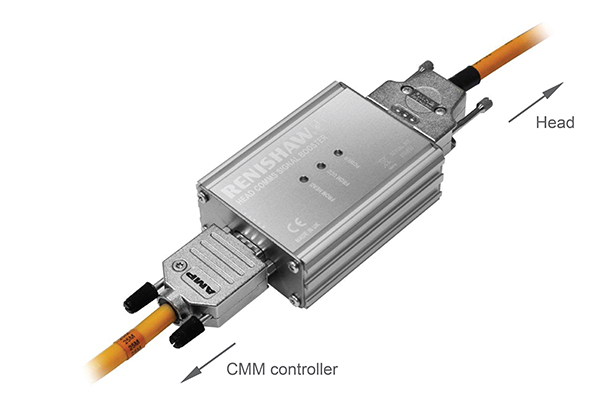
Head comms signal booster box installation
When using the Renishaw high-speed communications cable (orange cable) with Renishaw's 5-axis products, the maximum permissible cable length is 25 m. Where runs of greater than 25 m are needed between the machine controller and probe head, a head comms signal booster (HCSB) must be inserted. One HCSB is required for each additional 25 m of cable run.
The HCSB is powered from the machine cable so does not require an additional power supply. It simply connects between two machine cables as shown in the diagram below and can be attached to a suitable part of the machine structure if required.
Dimensions (L × W × H) | 91 mm × 64 mm × 32 mm |
|---|---|
Net weight | 161 g |
Power supply | 20 Vdc supplied via machine cable |
Connectors | 15-way high-density 'D' type plug connects to cable from controller 15-way 'D' type socket connects to cable from head |
Cable connections
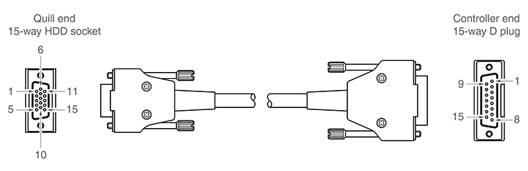
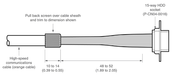
The cable connection to the head uses a standard 15-way high-density D connector. The cable should be connected and terminated as detailed below. It is mandatory that the Renishaw universal machine cable is used.
Various lengths of cable are available and include pre-crimped options for ease of installation.
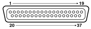
The following image shows the pin numbers for each connector end view of the Renishaw universal machine cable.
| 15-way HDD socket pin number (quill) | Function | Core colour | 15-way D plug pin number (controller) |
|---|---|---|---|
11 | Comms D+ | Green | 1 |
2 | 0 V | Black | 2 |
1 | Comms U+ | Orange | 3 |
7 | 0 V | White | 4 |
13 | Motor B0 | Blue | 5 |
3 | +20 V | Red | 6 |
4 | Motor A2 | Grey | 7 |
10 | Motor A0 | Pink | 8 |
9 | 0 V | Inner screen * | 9 |
12 | Comms D- | Green / black | 10 |
6 | Comms U- | Orange / black | 11 |
8 | +20 V | Clear | 12 |
14 | Motor B1 | Violet | 13 |
15 | Motor B2 | Yellow | 14 |
5 | Motor A1 | Brown | 15 |
Shell | Outer screen | Shell |
* NOTE: In pre-crimped cables this will be yellow / green.
Ensure that the inner screen is not shorted to the outer screen at either end of the cable. A short can be prevented by using a small piece of heatshrink or other suitable method.
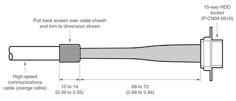
Preparation of Renishaw universal machine cable for quill mounted systems
Preparation of Renishaw universal machine cable for shank mounted systems
Temperature compensation connector
Pin number | Channel | Pin number | Channel |
|---|---|---|---|
1 | Channel 1 input | 20 | Channel 1 return |
2 | Channel 2 input | 21 | Channel 2 return |
3 | Channel 3 input | 22 | Channel 3 return |
4 | Channel 4 input | 23 | Channel 4 return |
5 | Channel 5 input | 24 | Channel 5 return |
6 | Channel 6 input | 25 | Channel 6 return |
7 | Channel 7 input | 26 | Channel 7 return |
8 | Channel 8 input | 27 | Channel 8 return |
9 | Channel 9 input | 28 | Channel 9 return |
10 | Channel 10 input | 29 | Channel 10 return |
11 | Channel 11 input | 30 | Channel 11 return |
12 | Channel 12 input | 31 | Channel 12 return |
13 | Channel 13 input | 32 | Channel 13 return |
14 | Channel 14 input | 33 | Channel 14 return |
15 | Channel 15 input | 34 | Channel 15 return |
16 | Channel 16 input | 35 | Channel 16 return |
17 | Reserved | 36 | Reserved |
18 | Reserved | 37 | Reserved |
19 | Reserved | Shell | GND |
The thermistors for each channel connect between the CH input and CH return numbers. The return signals are NOT zero volts and MUST NOT be connected to any zero volt signal, GND or screen.
NOTE: For more information regarding the set up and usage of axis and work piece sensors, please read the temperature compensation page of this installation guide.