Navigation
System installation and connection drawings
The illustrations in this section give information on system installation.
Kinematic joint installation and alignment
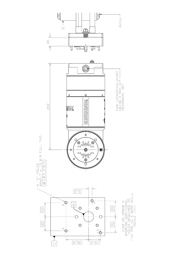
The PHS-2 head must be aligned to the axes of the machine to ensure correct operation with the ACR2 autochange rack. This section describes how to perform plane and rotational alignment of each axis of the head.
D-axis alignment in the horizontal plane
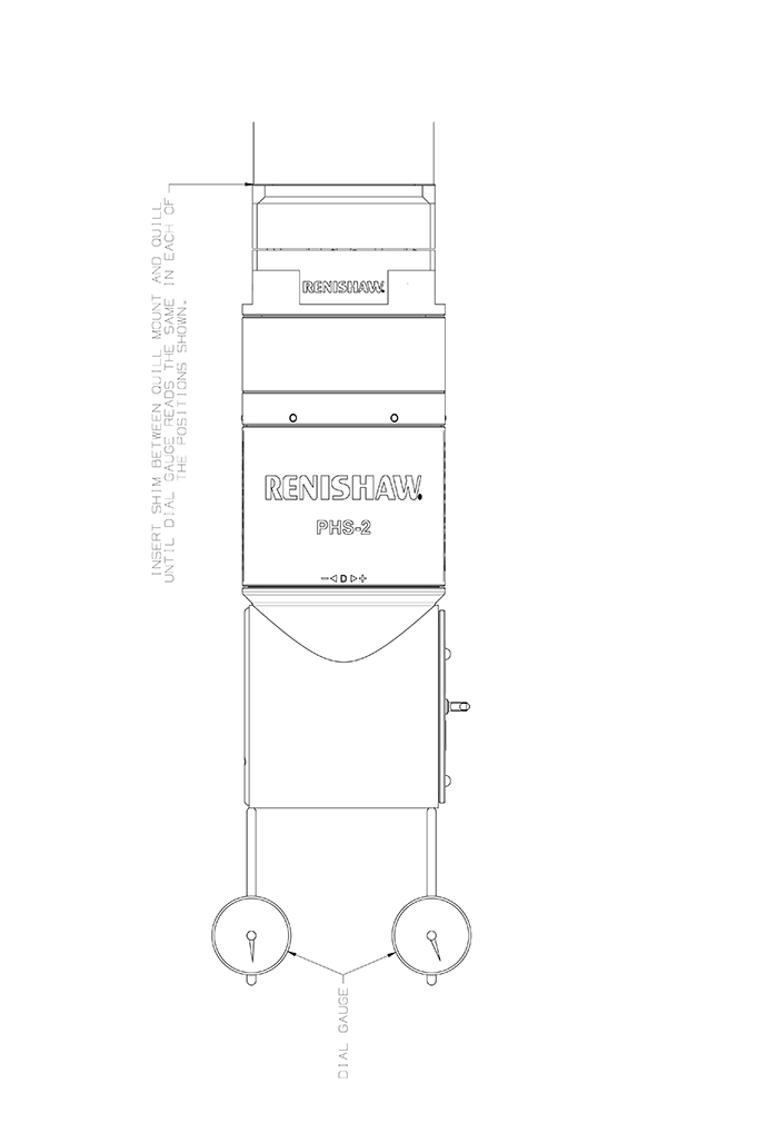
The head must be aligned with the machine axes so that the mounting holes in the probe arm are aligned with the pins of the ACR2 ports.
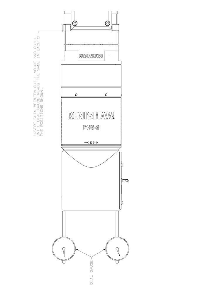
The head must be aligned to within ±0.1° of the CMM axes. It may be necessary to place shims between the kinematic quill mount and the CMM quill to achieve this.
The plane alignment of the D-axis can be checked by clocking the head as shown.
Plane alignment of the D-axis:

D-axis alignment in the vertical plane
This does not need to be accurately aligned as the rotation in the E-axis can compensate for any misalignment.
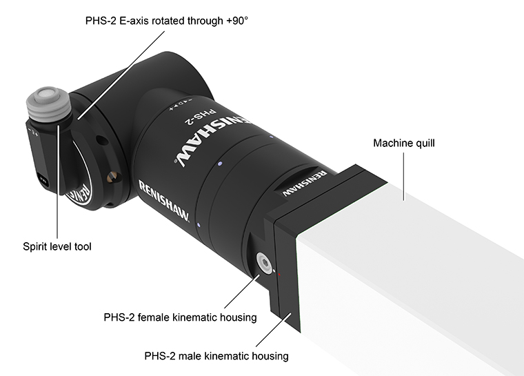
Axis rotation
Rotational alignment of the head axes can be found by using the spirit level tool (A-2150-1070). The spirit level should be screwed into a HA8 PHS M8 arm and the arm mounted onto the head. The following procedure describes the method of calculating the individual axes offsets.
- Rotate the E-axis through +90°.
- Make small adjustments in the D-axis and E-axis until the bubble indicates the head is level.
- With the head axes aligned to the CMM axes, subtract the initial rotation of +90° in the E-axis from the E-axis levelled position.
- These positions are now the angular offsets of each head axis from the datum position.
- Store these positions in software for that particular head.
Calculation of the individual head axis offsets:
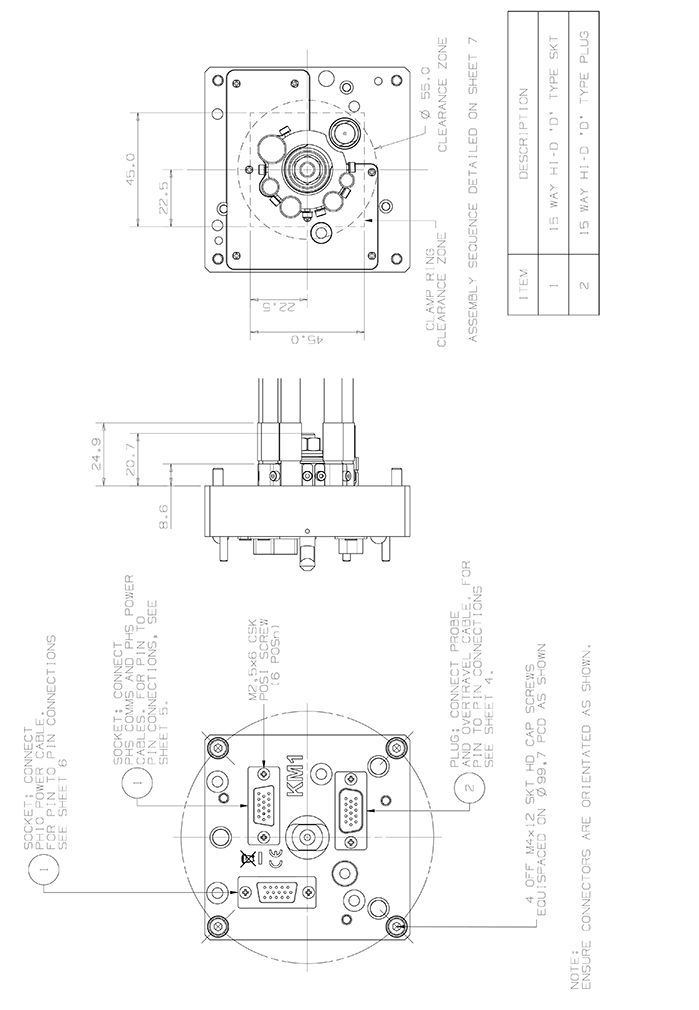
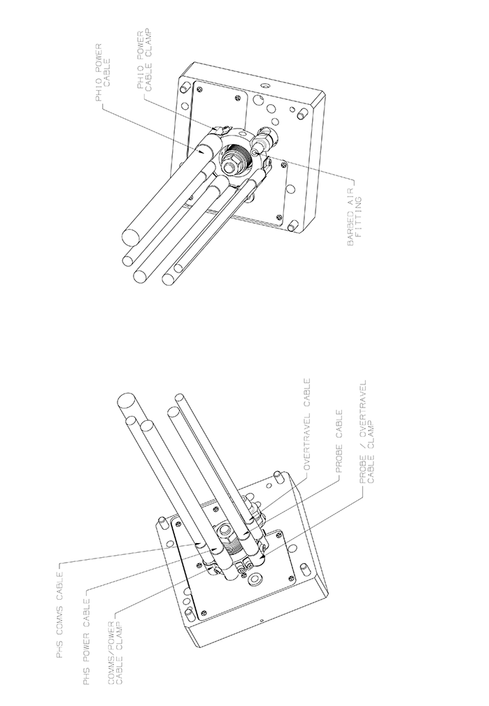
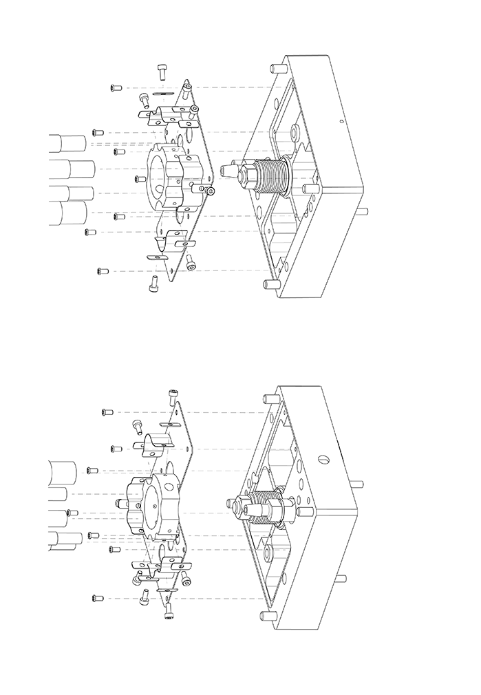
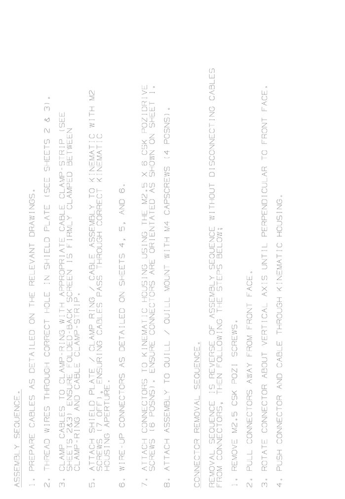
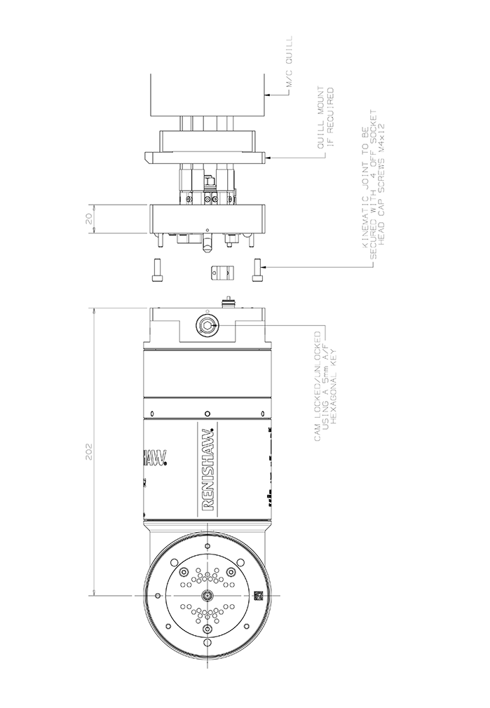
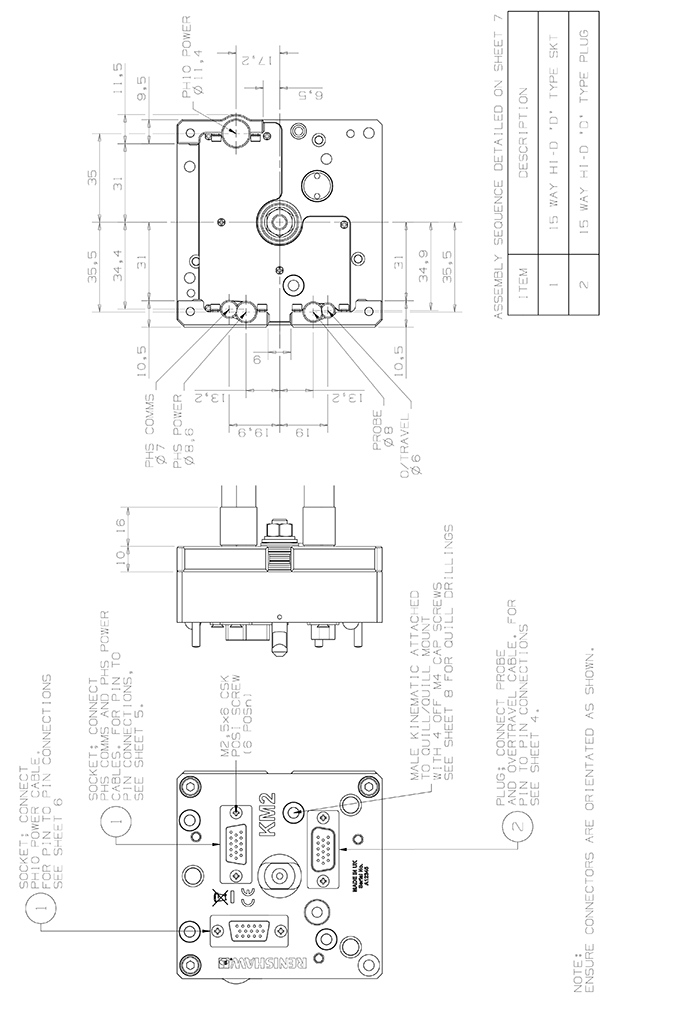
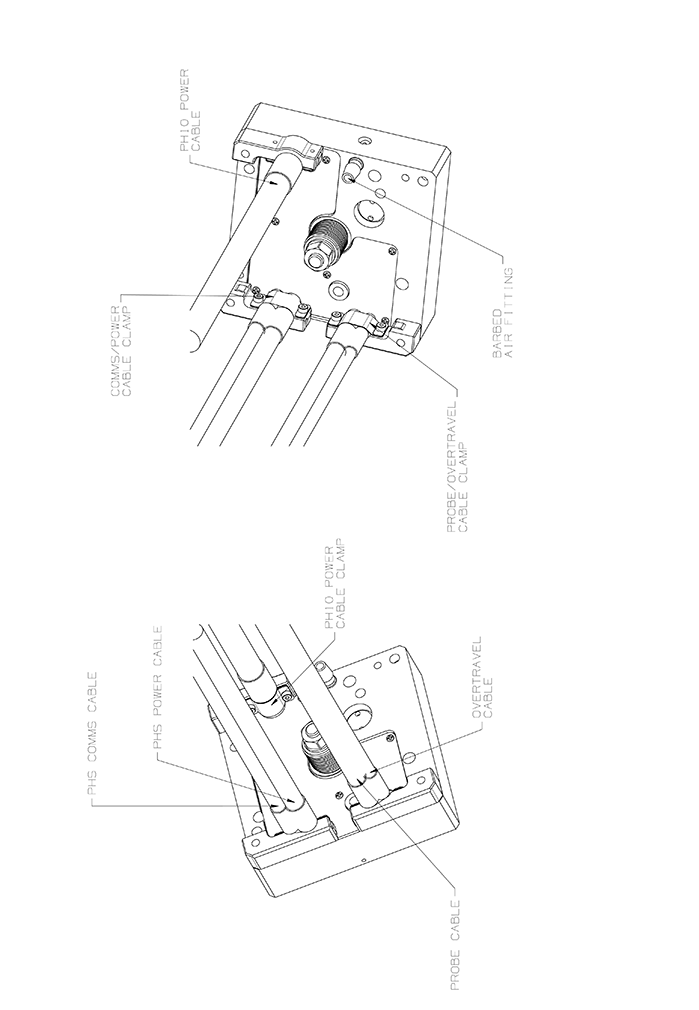
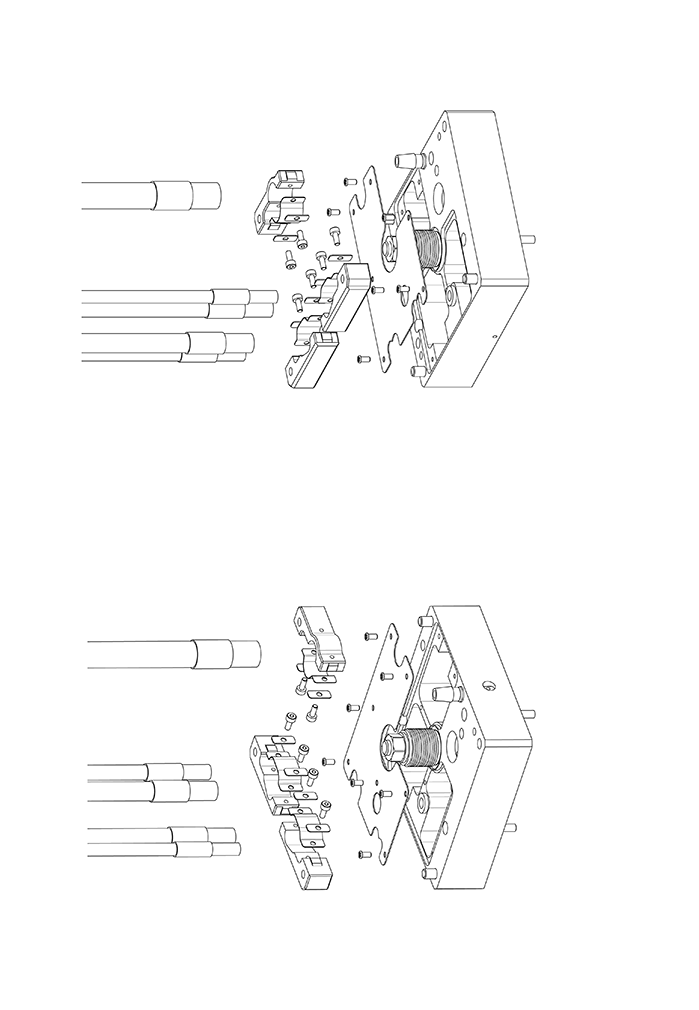
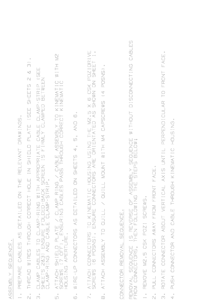
Kinematic joint installation and cable connections
The following pages show information on kinematic joint variations and cable installations.
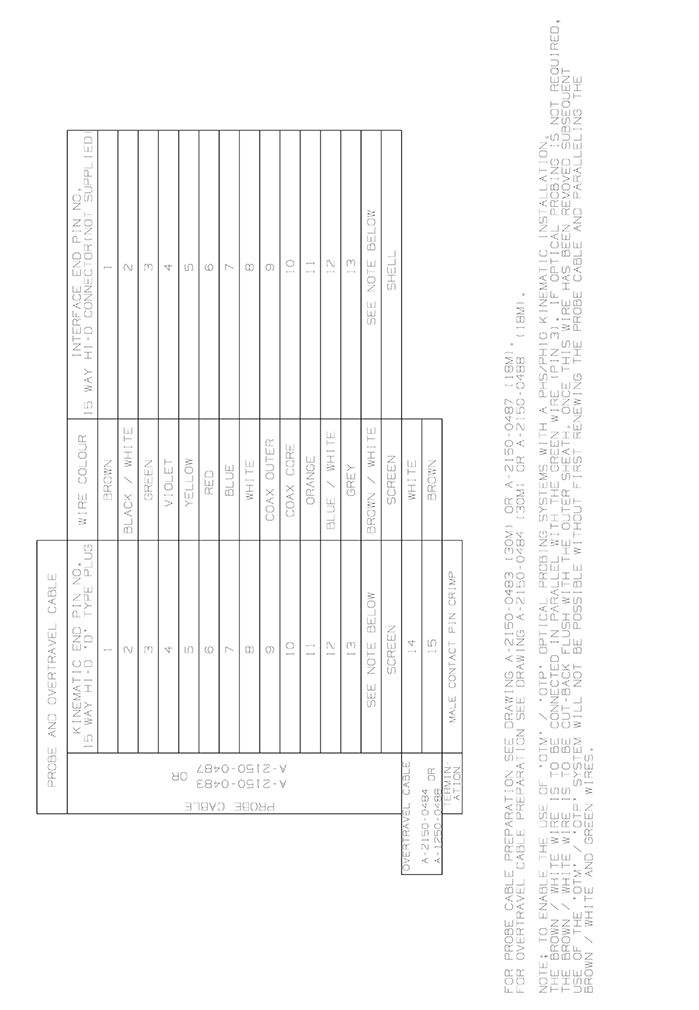
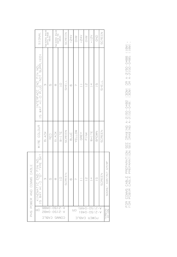
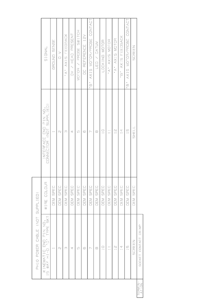
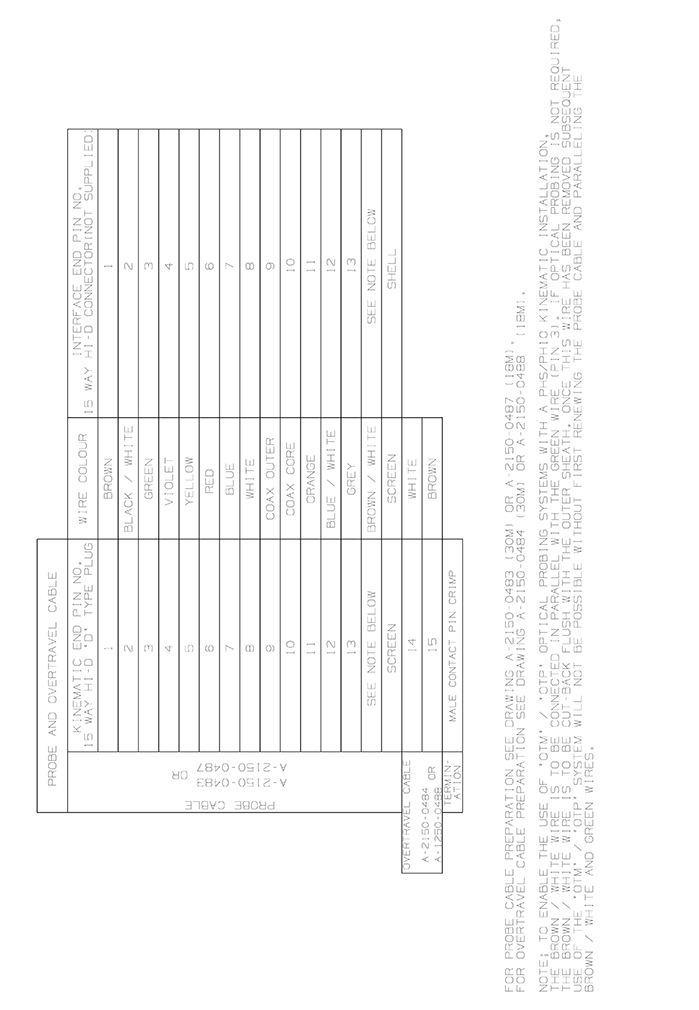
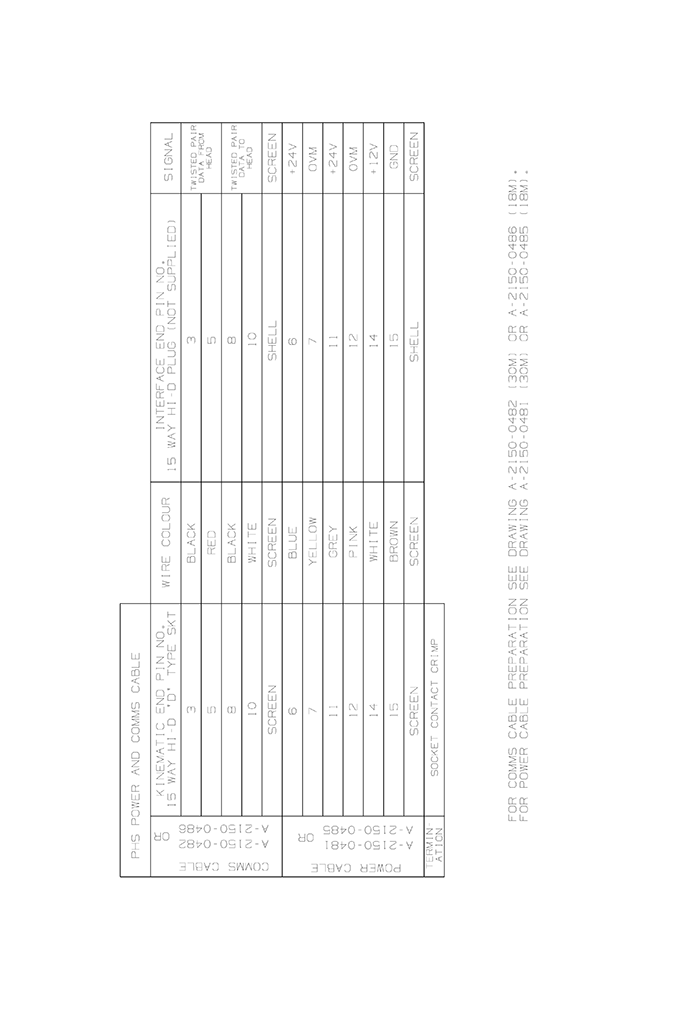
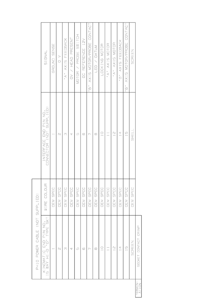
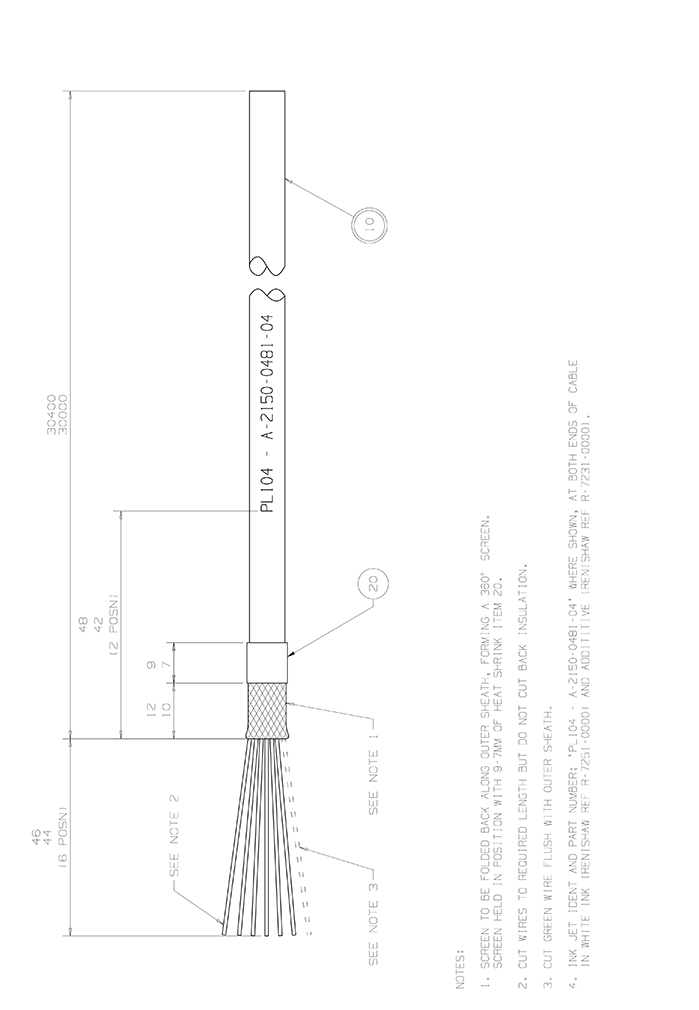
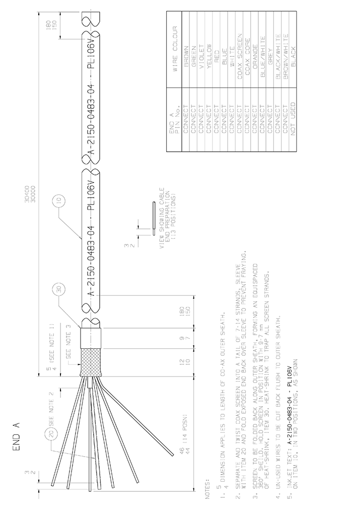
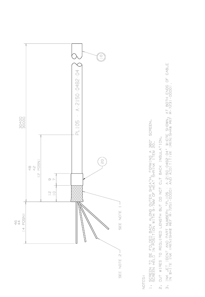
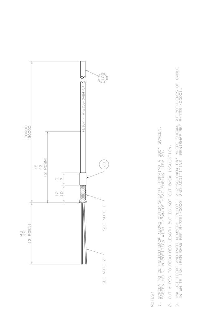
Cable connections
There are four individual cables in the PHS-2 system:
- Power cable
- Comms cable
- Probe cable
- Overtravel signal cable
Maximum cable length is 30 m.
NOTE: It is recommended that the resistance of the power cable should be typically 3 W but should not exceed 5 W total loop resistance as a thermal fuse and switch mode power supply are configured to monitor the correct voltage to the head. High cable resistance may trigger the thermal fuse.
This is usually evident by the symptom of a brief power up, approximately 1 or 2 seconds, where the head LED lights before extinguishing. Exchanging heads may appear to solve the problem however this is usually due to electrical tolerance differences between systems.