Navigation
Fitting the MRS feet
Fitting the MRS feet to the CMM
The MRS feet should be fitted to the CMM table along either the X or Y axis. The following procedure details the installation.
- Place the MRS foot (item 3 in illustration below) on the CMM table and position it over the chosen mounting hole. The feet do not require any rotational alignment.
- Two pairs of screws are supplied with the MRS*, one pair of M10 and one pair of M8 (item 1) with washers (item 2). The appropriate screw size should be used to secure the MRS foot to the CMM table.
- Tighten the bolt using the hexagonal key supplied.
- Fit the second foot at the appropriate distance along the chosen axis following steps 1 to 3 above.
* If the bolts supplied do not fit the CMM table then suitable alternatives should be found.

Key | Description |
1 | Screw |
2 | Washer (optional) |
3 | MRS foot |
Aligning the MRS feet to a CMM axis
To ease installation of the rail to the MRS it is recommended that the MRS feet be aligned to a CMM axis. The procedure is as follows:
- Measure the internal diameter of one of the MRS feet and make this a datum.
- Measure the internal diameter of the other MRS foot.
- Calculate the out-of-position angle of the MRS feet using the following formula:
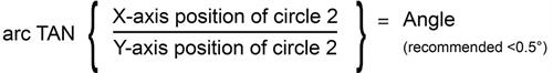
If the angle exceeds 0.5° then adjustment is necessary. Changing the relative foot position is achieved by releasing the bolt that holds the foot to the CMM table, moving the foot and then re-tightening the bolt. Steps 1 to 3 above should then be repeated.