Navigation
MCG setting-up
MCG cleanliness
The pivot ball, probe stylus and arm forks must be scrupulously cleaned before assembly as even a fingerprint can give an error of 3 microns. Use a proprietary cleaner to clean the surfaces of these components.
MCG temperature
The components of the MCG are subject to distortion due to changes in temperature. It is therefore important that handling of the components is kept to a minimum and that, if handled, a five-minute temperature stabilisation period is observed once any handling is complete. It is also recommended that the MCG is left in the vicinity of the CMM prior to performing any checking.
MCG mounting
For optimum performance, it is recommended that the MCG is clamped by its base to the table of the CMM prior to use. The recommended procedure is as follows:
NOTE: The MCG is not suitable for use with TP7M, SP600, SP80 or REVO RSP3 probes, and not recommended for use with TP200 probes. SP25M requires a TM25-20 and TP20 module. It is possible to use REVO with an RSP2 and RSH175 or RSH250 but only with the dedicated UCCassist-2 MCG routine.
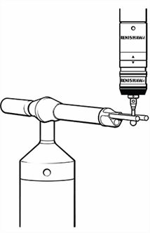
1. Attach the special, calibrated stylus of the MCG (this can be readily identified by the two grooves cut within the stylus stem) to your touch-trigger probe. If necessary, use the extensions and adaptors supplied to allow the calibrated stylus to be fitted to the probe.
Adaptors and extensions:
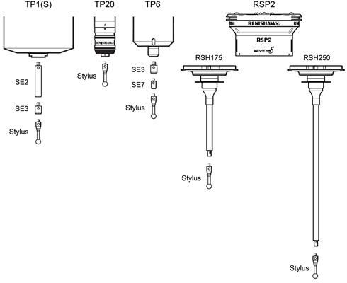
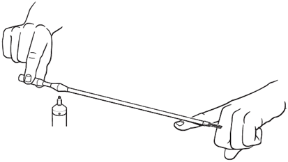
2. Visually inspect the stylus ball of the calibrated stylus for contamination and clean if required.
3. Inspect the probe head to ensure that it is securely located in the machine quill.
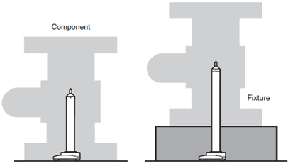
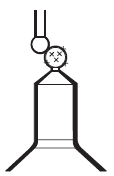
4. Construct a tower using the base, pillars and pivot. When building the tower, ensure that the pivot ball height will be approximately half the height of the component to be measured. If the component is mounted on a fixture, take any added height into account. Tighten the pillars by hand.
Building the tower:
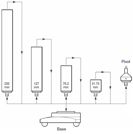
5. Towers of varying heights are possible by using the pillars in combinations as required.
Available pillar extensions:
NOTE: It is recommended that when mounting the tower to the CMM table that the base of the tower is clamped on the central steel clamping ring.
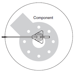
6. Ensuring that base of the tower is approximately central to the component volume, position the tower on the table of your CMM.
Positioning the tower:
7. Ensure that the ball of the kinematic pivot location is perfectly clean.
8. Allow the assembly to thermally stabilise for 2 minutes.
9. Datum the ball of the kinematic pivot location using a minimum of (10) ten readings. Set the centre of the pivot ball to be the origin (i.e. X=0, Y=0, Z=0).
Datuming the ball of the kinematic pivot location:
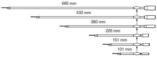
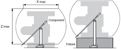
10. Select an arm radius R to suit the component. Use the following table to choose the correct arm for your component.
| Arm | Radius | X maximum | Z maximum |
|---|---|---|---|
| 1 | 101 mm (4 in) | 143 mm (5.6 in) | 143 mm (5.6 in) |
| 2 | 151 mm (6 in) | 213 mm (8.4 in) | 213 mm (8.4 in) |
| 3 | 226 mm (9 in) | 320 mm (12.7 in) | 320 mm (12.7 in) |
| 4 | 380 mm (15 in) | 537 mm (21.2 in) | 537 mm (21.2 in) |
| 5 | 532 mm (21 in) | 752 mm (29.6 in) | 752 mm (29.6 in) |
| 6 | 685 mm (27 in) | 986 mm (38.1 in) | 986 mm (38.1 in) |
11. Visually inspect the chosen counterbalanced arm for cleanliness. Make sure that the stylus guide rods and ball of the measuring location and the three ball pivot location are perfectly clean. If necessary, clean the parts with a suitable proprietary cleaner.
Arm length selections:
Angle of rotation:
NOTE: When position the counterbalanced arm on the pivot ball, it is important to ensure that handling of the arm is kept to an absolute minimum to avoid thermal distortion.
12. Locate the counterbalanced arm on the pivot ball.
13. Locate the stylus ball between the stylus guide rods.
14. Allow the assembly to thermally stabilise for a minimum period of 5 minutes.
Mounting the counterbalance arm:
Locating the stylus ball between the stylus guide rods:
Additional weights
Each counterbalanced arm is set to provide a downforce on the stylus ball which is sufficient to allow the probe and the arm to be moved without causing false triggers.
If required, the downforce may be increased by attaching additional weights to the counterbalanced arm to allow greater speeds and / or acceleration to be used.