Navigation
Product description and pin outs
Technical description
The PI 7-3 automatically recognises the probe type, determines the probe status, which is either triggered or seated (armed), and transmits debounced signals to the CMM controller. Status and control signals are transferred between the PI 7-3 interface, other Renishaw equipment and the CMM controller via the product interconnection system (PICS) ports.The TP7M probe series employ silicon strain sensors to detect the small gauging forces applied to the stylus tip. There is no electronic processing in the probe and the sensors are connected directly to the interface via the Renishaw autojoint connector, the probe head and associated wiring. The sensor signals are amplified and the resultant ‘probe signals', proportional to changes of strain, are compared with reference voltages to determine the status of the probe.
The initial value of strain in the sensor structure will vary with the mass of the stylus and the orientation of the probe. At switch-on or following re-orientation of the probe on a movable head, a process known as ‘autozero' is used to rapidly null the strain to a zero reference level.
When the stylus contacts the workpiece, a change of strain occurs in the probe structure causing the probe signal voltage to exceed the trigger reference level. A probe trigger signal condition occurs by asserting SYNC on the PICS port. As stylus deflection increases, the probe signal voltage will exceed the halt reference level and HALT will be asserted on the PICS port. When the stylus backs-off the workpiece, the probe signal falls below the reference levels; SYNC and HALT are cleared to the seated state and the sensor outputs are nulled to the zero reference level in preparation for the next trigger. Debounce timers allow the motion characteristics to stabilise after the initial trigger and reseat events, to prevent spurious switching.
A solid state relay (SSR) equivalent of the SYNC output is provided for controllers requiring a voltage free contact at their probe input.
There is a choice of two levels of trigger sensitivity to allow the TP7M series to be used on a wide range of CMM types or in situations where the ambient vibration levels are not ideal.
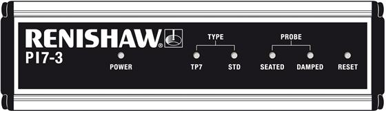
Front panel indicators
Indicator |
| Colour | Function |
|---|---|---|---|
POWER | ON | Green | Mains power on |
TYPE | STD | Green | Touch-trigger probe selected |
| TP7 | Green | TP7M series probe selected |
PROBE | SEATED | Green | ON - probe (seated) |
|
|
| OFF - probe triggered or no probe connected |
| DAMPED | Yellow | PDAMP asserted |
Reset switch
Automatically, the probe will reset to the armed state when the PI 7-3 is powered up. Occasionally, it may be necessary to perform a manual reset, for example after changing the probe stylus.
Press the RESET button on the front panel for two seconds to reset the probe to the armed (seated) state.
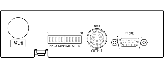
Configuration switches
Switch no. | Function | Position | Description |
|---|---|---|---|
1 | SSR invert | UP | SSR closed when probe seated |
| DOWN | SSR open when probe seated | |
2 | Buzzer | UP | Audible indication of probe trigger - OFF |
|
| DOWN | Audible indication of probe trigger - ON |
3 | Kinematic probe input | UP | Autojoint input only |
|
| DOWN | PICS input enabled |
4 | Probe type | UP | Optimise for issue '01' (or later) probe |
|
| DOWN | All probe types |
5 | STOP disable | UP | No response to PICS - STOP |
|
| DOWN | Trigger outputs respond to PICS - STOP |
6 | HALT invert | UP | PICS - HALT output active HIGH |
|
| DOWN | PICS - HALT output active LOW |
7 | HALT mode | UP | HALT generated internally |
|
| DOWN | HALT asserted by PICS |
8 | Auto reset | UP | Probe will reset after 2 seconds |
|
| DOWN | Automatic reset disabled |
9 | Trigger sensitivity | UP | Level 2 (mid sensitivity) |
|
| DOWN | Level 1 (high sensitivity) |
10 | Extended debounce | UP | Custom settings as per special product A-1073-0544 |
| DOWN | Standard mode |
NOTE: When switch 7 is set to ‘HALT generated internally' the PICS IN connector pin 6 becomes a 150 Ω pull up resistor to 5 V, to be used to connect to the PICS STOP signal if required.
Switch 1
The solid state relay (SSR) output contacts may be set to be open when the probe is seated and closed when the probe is triggered. The output may be inverted to mimic the action of a kinematic probe.
Switch 2
The internal audible indicator normally gives a short tone burst when the SYNC output changes from the seated to the triggered state. The switch may be set to enable or disable the sound.
Switch 3
With switch 3 UP, the PI 7-3 will automatically change operating modes from TP7M to kinematic probe types (TP2, TP20 or TP6 / TP6A) when a TP6A probe or PAA series adapter is attached to the Renishaw autojoint connector on the probe head. Switch 3 should be set to the DOWN position only when it is necessary to connect a kinematic probe or an electronic trigger, from an external source, to the PICS input connector. For example, this will be necessary if the TP7 is fully integrated with the TP200 probe on the same installation.
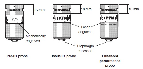
Switch 4
Early versions of the TP7M probe required faster resetting than the ‘01' (or later) issue (after January 1995). Where only the ‘01' or later versions are to be used, switch 4 should be set to the UP position to optimise the reset function. This will reduce the possibility of an incorrectly seated probe occurring in situations where the back-off from the gauge point is slow or where the stylus ‘skates' on the surface. Switch 4 should be set to the DOWN position where the ‘pre-01' probe or mixed types are used. The DOWN position provides equivalent function to previous versions of the PI 7.
The TP7M probe types may be recognised by the differences in appearance shown below.
Switch 5
With switch 5 DOWN, the SYNC, HALT and SSR outputs will go to the triggered state when the CMM controller or other Renishaw equipment asserts the PICS STOP line. Setting switch 5 UP disables the response.
Switch 6
The HALT output at the PICS connector is active low with switch 6 DOWN but may be inverted by selecting switch 6 UP.
Switch 7
Set switch 7 to the UP position for normal operation with the TP7M or kinematic probes (TP2, TP20 or TP6/TP6A). For fully integrated operation of the TP7M with the TP200 probe on the same installation, set switch 7 to the DOWN position to allow the HALT signals from the PI 200 interface to be automatically routed to the CMM controller when the probe is changed.
Switch 8
Set switch 8 DOWN for normal operation with the automatic reset disabled. Set switch 8 UP to select automatic reseat of the probe 2 seconds after triggering. This facility is included for compatibility with previous versions of the PI 7.
Switch 9
Set switch 9 DOWN for normal operation with the TP7M at its highest sensitivity (level 1) and lowest error.
Under certain conditions, vibration may cause false ‘air' triggers during gauging and it may be necessary to reduce the probe's sensitivity. False triggers may occur when large or heavy stylus arrangements are used, or where there is floor transmission from nearby machinery or vehicles. Set switch 9 UP to select level 2. This will reduce sensitivity to vibration but with a small loss of measuring accuracy.
Switch 10
Set switch 10 UP to operate as the custom product A-1073-0544 which has a modified debounce time.
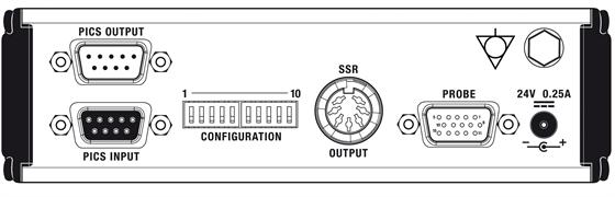
Connector pins
Refer to the Renishaw installation guide ‘Product interconnection system – PICS' (part number H-1000-5000) for the electrical specification of the PICS signals.PICS output connector
The PICS output connector is a 9 pin ‘D' type plug. The pin numbers (viewed on the rear panel) are shown in the table below.
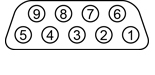
| Pin no. | Function | Pin no. | Function |
| 1 | STOP | 6 | HALT |
| 2 | PPOFF | 7 | PDAMP |
| 3 | 0 V | 8 | LEDOFF |
| 4 | Reserved for Renishaw use | 9 | Not used |
| 5 | SYNC (probe trigger) | Shell | Screen |
PICS input connector
The PICS input connector is a 9 pin ‘D' type socket. The pin numbers (viewed on the rear panel) are shown in the table below.
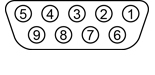
Pin no. | Function | Pin no. | Function |
|---|---|---|---|
1 | STOP | 6 | HALT IN |
2 | PPOFF | 7 | PDAMP |
3 | 0 V | 8 | LEDOFF |
4 | LED anode | 9 | Probe return (0 V) |
5 | Probe input | Shell | Screen |
Solid state relay (SSR) connector
The SSR output connector is a 7 pin DIN socket. The pin numbers (viewed on the rear panel) are shown in the table below.
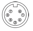
Pin no. | Function | Pin no. | Function |
|---|---|---|---|
1 | 0 V | 5 | Probe status 2 |
2 | Not used | 6 | Not used |
3 | Not used | 7 | Not used |
4 | Probe status 1 | Shell | Screen |
Probe multiwire cable
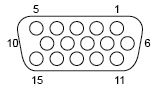
Pin no. | Function | Pin no. | Function |
|---|---|---|---|
1 | REF GAUGE | 9 | NC |
2 | 0 V | 10 | NC |
3 | TP2 RETURN | 11 | GAUGE 1 |
4 | GAUGE 2 | 12 | NC |
5 | GAUGE 3 | 13 | TP2 INPUT |
6 | +5 V | 14 | HEAD POSITIVE |
7 | -5 V | 15 | HEAD LED RETURN |
8 | PROBE ID | Shell | SCREEN |
Dimensions
Enclosure style | 1/3 rack (19 inch) × 1U |
|---|---|
Overall dimensions | 155 mm × 44 mm × 180 mm |
Mounting method | Rack mounting or free standing |
Weight | 1.25 kg |