Navigation
RFP1 installation
NOTE: Please refer to the REVO-2 change port system spacing guide (Renishaw part number H-1000-5408) for full details of the recommended spacing for positioning all sensors and artefacts on the MRS / MRS2 rail.
Fitting VPCP to the MRS / MRS2 rack
The VPCP heated change ports can be fixed to an MRS or MRS2 rack system. It is recommended that they are attached to the MRS / MRS2 rail using the following procedure, where it is assumed that the MRS / MRS2 rack system is correctly installed.
- Insert one of the fixing screws through the VPCP.
- Position the VPCP underneath the rail and locate the respective T-nut within the rail*.
- Hand tighten the fixing screw into the T-nut and repeat the process for the next fixing screw.
- Position the VPCP and tighten both fixing screws using the hexagonal key supplied.
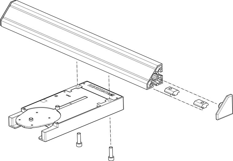
* NOTE: T-nuts must be used with the MRS system. However T-nuts and D-nuts are compatible with the MRS2 system.
Connecting VPCP to PSU
Using a PSU other than the one supplied by Renishaw is not recommended.
DC extension cables are available for the PSU but the length should not exceed 15 m otherwise the performance can be affected.
It is possible to power up to four REVO system ports with one PSU using the daisy-chain technique shown below.
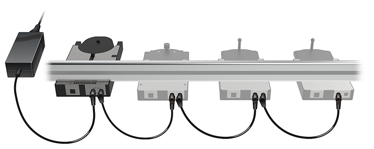
NOTE: Nothing other than VPCP or other REVO system ports should be connected to the PSU. No more than four can be powered from one PSU. No more than one PSU should be connected to a daisy chain of ports. Ports need to be next to each other on the MRS2 rail for daisy chaining. Power can be connected to either end of the daisy chain. Turn off or disconnect the mains supply to the PSU before fitting DC power cables to the ports.
Spares
| Part description | Renishaw part number |
| DC daisy-chain cable | P-CA82-0019 |
| DC extension cable (1.5 m) | A-3060-0016 |
| PSU | P-EA02-0021 |
| DC extension cable (5 m) | A-3060-0017 |
| DC extension cable (10 m) | A-3060-0018 |
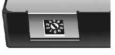
VPCP switch settings
The temperature can be set using the rotary switch on the rear of the port:
| Position | Description |
| 0 - 3 | Reserved for future use |
| 4 (factory set) | Suitable for specified system ambient temperature |
| 5 - 9 | Reserved for future use |
NOTE: Please do not change the settings without contacting your supplier.
CAUTION: This unit is not sealed. Please do not insert anything into the gaps under the port lid as it can cause damage to internal components within the product.