Navigation
System installation
Cable connections
The cable connection to the head uses a standard 15-way high-density D connector. The cable should be connected and terminated as detailed below. It is mandatory that the Renishaw universal machine cable is used.
Various lengths of cable are available and include pre-crimped options for ease of installation.
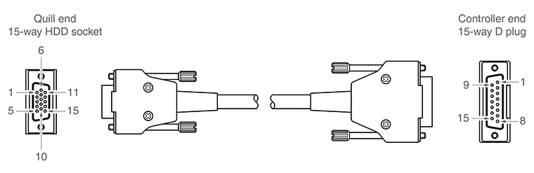
The following image shows the pin numbers for each connector end view of the Renishaw universal machine cable.
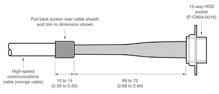
Preparation of Renishaw universal machine cable for quill mounted systems
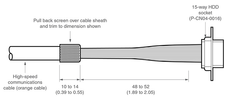
Preparation of Renishaw universal machine cable for shank mounted systems
15-way HDD socket pin number (quill) | Function | Core colour | 15-way D plug pin number (controller) |
|---|---|---|---|
11 | Comms D+ | Green | 1 |
2 | 0 V | Black | 2 |
1 | Comms U+ | Orange | 3 |
7 | 0 V | White | 4 |
13 | Motor B0 | Blue | 5 |
3 | +20 V | Red | 6 |
4 | Motor A2 | Grey | 7 |
10 | Motor A0 | Pink | 8 |
9 | 0 V | Inner screen * | 9 |
12 | Comms D- | Green / black | 10 |
6 | Comms U- | Orange / black | 11 |
8 | +20 V | Clear | 12 |
14 | Motor B1 | Violet | 13 |
15 | Motor B2 | Yellow | 14 |
5 | Motor A1 | Brown | 15 |
Shell | Outer screen | Shell |
* NOTE: In pre-crimped cables this will be yellow / green.
Ensure that the inner screen is not shorted to the outer screen at either end of the cable. A short can be prevented by using a small piece of heatshrink or other suitable method.
Mounting
The following illustrations show the range of mounting adaptors that have been developed for use with PH20. Other variants can be manufactured on request, please contact Renishaw for further information.
Shank mounting adaptor
The PH20 can be mounted to a CMM using the standard range of CMM shanks. The shank mounting adaptor enables the standard range of CMM shanks to be easily fitted to the PH20.

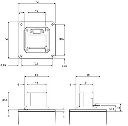
Small quill (60 mm square)
This adaptor is designed to allow you to drill the required hole for mounting to your CMM quill yourself. If provided with this information we can create and supply a pre-drilled version of this to meet your requirements.
The head cable comes out of the top of the quill adaptor.

Large quill (80 mm square)
This adaptor is designed to allow you to drill the required hole for mounting to your CMM quill yourself. If provided with this information we can create and supply a pre-drilled version of this to meet your requirements.
The head cable exits from the top of the quill adaptor.

PH10MQ PLUS adaptor
The PH10MQ PLUS adaptor for PH20 allows the PH20 to be fitted to any machine that currently features a PH10MQ PLUS.
Fitting PH20 to CMM quill
CAUTION: The PH20 head must be mounted so that the LEDs on the front of the head are facing towards the negative Y-axis of the CMM.
1. Lower the CMM quill to a position where the head can be fitted.
NOTE: It is recommended that the PH20 box is put under the quill and covered with something soft in order to minimise any damage should the PH20 be accidentally dropped during fitment to the quill.
2. Route the cable through the appropriate quill adaptor and clamp cable screen in place.
3. Fit the adaptor to the quill of the machine.

Depending upon the type of PH20 quill adaptor being used, it may be necessary to fit the PH20 to the quill adaptor before fitting it to the CMM.
4. Secure the D-type connector between the two plates in the side of the quill adaptor using the screw provided.

5. Push the head onto the quill adaptor ensuring that the connectors mate correctly.
6. Secure in place with the appropriate fixing screws.

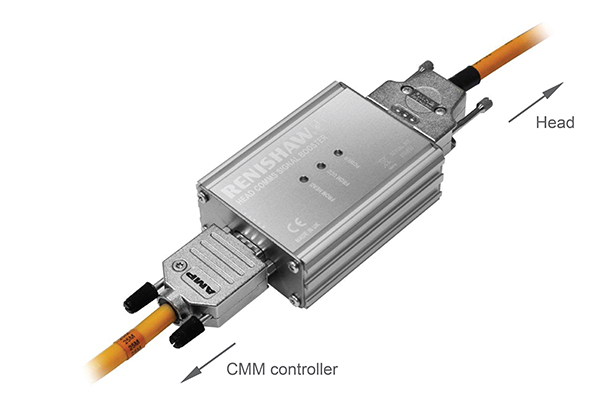
Head comms signal booster box installation
When using the Renishaw high-speed communications cable (orange cable) with Renishaw's 5-axis products, the maximum permissible cable length is 25 m. Where runs of greater than 25 m are needed between the machine controller and probe head, a head comms signal booster (HCSB) must be inserted. One HCSB is required for each additional 25 m of cable run.
The HCSB is powered from the machine cable so does not require an additional power supply. It simply connects between two machine cables as shown in the diagram below and can be attached to a suitable part of the machine structure if required.
Dimensions (L × W × H) | 91 mm × 64 mm × 32 mm |
|---|---|
Net weight | 161 g |
Power supply | 20 Vdc supplied via machine cable |
Connectors | 15-way high-density 'D' type plug connects to cable from controller 15-way 'D' type socket connects to cable from head |
PH20 UCC license key
PH20 has its own unique license key for the UCC controller. Prior to commencing the installation sequence, the PH20 UCC license key must be activated by following the instructions on leaflet H-1000-1244 that is included within the PH20 UCC kit.
PH20 initialisation and commissioning sequence
The PH20 system should be commissioned using Renishaw's UCCassist-2 software. PH20 specific sequences have been created for the commissioning of the head.
The PH20 will be shipped with installation parameters stored inside the head. These parameters (hed files) are unique to the PH20 they are shipped with. If the hed file is lost / deleted, please go to www.renishaw.com/cmmsupport and click on the hed file tab to download. You will need to log in using RPS (you may need to register for this service) and then enter the head serial number to retrieve the correct hed file.
Alternatively contact your local Renishaw office, quoting the head serial number, to obtain a copy of the data file.
NOTE: Please do not modify the hed file stored inside the PH20 head.
PH20 calibration
The PH20 is not supplied with a datum sphere as standard but Renishaw recommends the use of A-1034-0026.
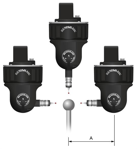
Minimum clearance required for calibration dimension A (in mm) | |
|---|---|
Standard force module | 102 |
Medium force module* | 102 |
Low force module* | 102 |
6-way module* | 106 |
EM1 module* | 152.5 |
EM2 module* | 177.5 |
The PH20 must be calibrated using the supplied stylus (A-5004-2182). It is recommended that the TP20 standard force stylus module is used for head calibration.